CARPET EXTRACTOR Operating Instructions MODEL: CDT7 Read these instructions before operating the machine MM 98626 07/28/05
MACHINE DATA LOG/OVERVIEW MODEL _______________________________________ DATE OF PURCHASE __________________________ SERIAL NUMBER ______________________________ SALES REPRESENTATIVE # _____________________ DEALER NAME ________________________________ OPERATIONS GUIDE NUMBER ___________________ PUBLISHED __________________________________________ YOUR DEALER Name: __________________________________________________________________________________________________ Address: __________________________________
TABLE OF CONTENTS Machine Data Log/Overview.........................1 Table of Contents..........................................2 HOW TO USE THIS MANUAL How to use this Manual.................................1-1 SAFETY Important Safety Instructions ........................2-1 Hazard Intensity Level ..................................2-2 Grounding Instructions..................................2-3 OPERATIONS Technical Specifications. ..............................3-1 Controls/Component Location ...........
HOW TO USE THIS MANUAL The SAFETY section contains important information regarding hazard or unsafe practices of the machine. Levels of hazards is identified that could result in product or personal injury, or severe injury resulting in death. This manual contains the following sections: - HOW TO USE THIS MANUAL SAFETY OPERATIONS MAINTENANCE PARTS LIST The OPERATIONS section is to familiarize the operator with the operation and function of the machine.
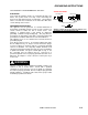
SAFETY INSTRUCTIONS IMPORTANT SAFETY INSTRUCTIONS When using an electrical appliance, basic precaution must always be followed, including the following: READ ALL INSTRUCTIONS BEFORE USING THIS MACHINE. This machine is for commercial use. ! WARNING: To reduce the risk of fire, electric shock, or injury: Connect to a properly grounded outlet. See Grounding Instructions. Do not leave the machine unattended. Unplug machine from outlet when not in use and before maintenance or service. Use only indoors.
HAZARD INTENSITY LEVEL The following symbols are used throughout this guide as indicated in their descriptions: HAZARD INTENSITY LEVEL There are three levels of hazard intensity identified by signal words -WARNING and CAUTION and FOR SAFETY. The level of hazard intensity is determined by the following definitions: ! WARNING WARNING - Hazards or unsafe practices which COULD result in severe personal injury or death.
GROUNDING INSTRUCTIONS THIS PRODUCT IS FOR COMMERCIAL USE ONLY. ELECTRICAL: In the USA this machine operates on a standard 15 amp 115V, 60 hz, A.C. power circuit . The amp, hertz, and voltage are listed on the data label found on each machine. Using voltages above or below those indicated on the data label will cause serious damage to the motors. GROUNDING INSTRUCTIONS: This appliance must be grounded.
TECHNICAL SPECIFICATIONS POWER TYPE GENERAL DIMENSIONS/WEIGHT ELECTRICAL: 115 V, 15 A, 60 HZ Vacuum shoe: 17” (43.18 cm) cast aluminum with spring loaded down pressure ELECTRIC VACUUM MOTOR: (1) –3 stage, 1 hp, 99 cfm (2.80 cubic meters/min.) Waterlift –117” (297cm) WHEELS: (2) 10” dia. (25 cm) wheels by 2” BRUSH: (1) 15” (38.1 cm.) SOLUTION PUMP: 73 PSI, diaphragm style, internal bypass WEIGHT: 92lbs. (42kg) LENGTH: 41” (104 cm) SOLUTION CAPACITY: 7 gallons (26.5ltr) HEIGHT: 34” (86.
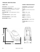
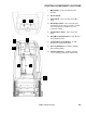
CONTROLS/COMPONENT LOCATIONS 1. Main Handle. Used to pull and maneuver machine. 2. Electrical Cord. 3 3. Pump Switch. Turns on pump and enables spray. 5 4. Brush/Spray switch. Turns on brush motor and activates electro-valve to dispense solution to floor through jets. Intermittent, off, and continuous settings. 5. Vacuum Motor Switch. Turns on vacuum motor 6. Brush Motor Circuit Breaker. 6 amp. Breaker protecting brush motor. 4 1 7. Vacuum Motor Circuit Breaker. 15 amp.
CONTROLS/COMPONENT LOCATIONS 1. Solution Accessory Tool Hookup. Used for various auxiliary cleaning tools. 2. Vacuum Hose Door. Used to connect various auxiliary 1 ½ inch cleaning tool vacuum hoses. 3. Brush Height Adjustment. Used to regulate brush height from storage position to various carpet heights. 10 4. Recovery Tank. Used to collect dirty cleaning solution. 5. Solution Tank. Used to hold cleaning solution. 1 6. Recovery Tank Dome. 7. Vacuum Shoe. 8. Brush Housing. 9. Front Lifting Handle.
CONTROLS/COMPONENT LOCATIONS 1. Solution Intake Cover. 2. Vacuum Intake Cover. 3. Float Shut-Off. 4. Clean-Out Opening. 5. Pour Spout. 6. Lift Handle.
FILLING OPERATIONS STEP 1 RECOVERY TANK Remove recovery tank SOLUTION TANK STEP 2 FILL LINE Add water 7 gal. (26.5 ltr.) 140°F (60°C) STEP 3 FILLING THE CADET NOTE: Use clean bucket of water to fill solution tank 7 – 14oz. (207ml – 414ml) Add cleaning chemical Do not put defoamer, solvents, spotter or prespray chemicals in the solution tank. Do not allow water to spill into vacuum motor inlet. Dry spillage from top of solution tank before replacing recovery tank.
OPERATIONS STEP 1 Remove electrical cord and literature from recovery tank. Fill solution tank (see filling operations, page3-5). STEP 2 Plug cord into grounded outlet. Note: Be sure dome is seated on recovery tank, and float shut-off is installed correctly. STEP 3 Adjust brush to proper setting. Note: For good operation the brush must skim the carpet. If circuit breaker trips raise brush to prevent damage to motor or carpet. STEP 4 Turn on both Vacuum and Pump motor switches (“ON”=“I”).
OPERATIONS Tip machine back by main handle to move to starting point. STEP 5 Lower machine to floor. STEP 6 Select intermittent or continuous switch setting to turn on brush and start solution spray. The intermittent setting requires the operator to hold the switch in the “on” position with the thumb, and is typically used in small areas where short cleaning passes are made.
CLEANING PROCEDURE 1ft. (30cm) STEP 1 Start at wall closest to power outlet. Pull straight back without pushing down on handle. STEP 2 Release intermittent setting or turn off continuous setting on brush/spray switch approximately 1 foot before ending cleaning pass. STEP 3 Push down on handle to raise vacuum shoe and brush before moving to the next cleaning pass. Overlap brush contact area approximately 1inch. OFF 1in.
CLEANING PROCEDURE Use right side of machine for cleaning against walls. STEP 5 After cleaning, turn off all controls, return brush to storage position and carefully unplug machine. STEP 6 OFF OFF OFF To speed drying, use a Windblower™ fan. STEP 7 Empty recovery tank by releasing dump hose. Use a hose with cold water to clean out the recovery tank. Also drain solution tank after each use.
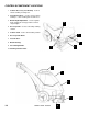
ACCESSORY TOOL USAGE STEP 1 Use only one of the following acceptable accessory tools. HT DDH DH 89227 89226 39504 Pull back collar and insert over machine mounted fitting, then release collar to lock into place. STEP 2 STEP PUMP VACUUM ON 3 Lift door on front of vacuum shoe and insert 1 ½ inch hose cuff into hole. Turn on Pump and Vacuum Switch. Note: Be sure intermittent/continuous switch is in center (off) position and brush is in storage position.
MAINTENANCE SERVICE SCHEDULE MAINTENANCE Check machine for cord damage Check recovery dome and gasket for damage and cleanliness Check brush – should be clean with no lint or strings attached Inspect vac shoe for blockage; remove fibers with coat hanger, etc.
MAINTENANCE PERIODIC MAINTENANCE Twice a month, flush a white vinegar solution (One quart vinegar to two gallons of water) or antibrowning solution (mixed as directed) through the extractor. This will prevent build-up of alkaline residue in the system. If spray jets become clogged, remove the spray tips, wash them thoroughly, and blow-dry. NOTE: Do not use pins, wire, etc. to clean nozzles as this could destroy spray pattern. Periodically inspect all hoses, electrical cables and connections on your machine.
MAINTENANCE ONLY QUALIFIED MAINTENANCE PERSONNEL ARE TO PERFORM THE FOLLOWING REPAIRS. ! WARNING: VACUUM MOTOR REPLACEMENT Vacuum Motor Carbon Brushes Replacement (Ametek) 1. Turn off all switches and unplug machine. End Cap 2. Remove recovery tank. 3. Remove the (2) screws that fasten the solution tank to the frame, and tilt tank back to expose the inside of the frame. Carbon Brushes WARNING: The green ground wire must be attached for safe operation. See wiring diagram. 4.
MAINTENANCE ONLY QUALIFIED MAINTENANCE PERSONNEL ARE TO PERFORM THE FOLLOWING REPAIRS. ! WARNING: BELT REPLACEMENT 1. Turn off all switches and unplug machine. 2. Remove recovery tank and brush. 3. Remove the (2) screws that fasten the solution tank to the frame, and tilt tank back to expose the inside of the frame. 4. Loosen the (4) screws that hold the brush motor in place and slide motor forward to release tension in belt. 5.
MAINTENANCE ! WARNING: ONLY QUALIFIED MAINTENANCE PERSONNEL ARE TO PERFORM THE FOLLOWING REPAIRS. SOLUTION PUMP REPLACEMENT 1. Turn off all switches and unplug the machine. 2. Remove recovery tank. 3. Remove the (2) screws that fasten the solution tank to the frame, and tilt tank back to expose the inside of the frame. 4. Remove solution hoses from fittings in pump. 5. Remove the (2) screws that fasten the pump to the frame. 6. Reverse process to install pump.
WIRING DIAGRAM CADET 98626 08/25/04 4-6
TROUBLESHOOTING CHART PROBLEM No Power, Nothing Runs Vacuum Motor Will Not Run Vacuum Motor Runs But Suction Is Poor Poor Or No Water Flow (Carpet Is Streaky) CAUSE Plug in cord. Reset breaker. Call for service. Call for service. Reset breaker. Call for service. Call for service. Call for service. Remove debris from vac shoe. .Dome gasket defective or missing. Vacuum hose cracked or hose cuff loose. Recovery tank full / float ball stuck in the up position. Main pump switch off. Replace as necessary.
MAINTENANCE THIS PAGE INTENTIONALLY LEFT BLANK.
FRAME ASSEMBLY 30 7 19 18 15 (SEE PG.
FRAME ASSEMBLY REF PART NO. QTY DAESCRIPTION 1 2 3 4 5 6 7 8 9 10 11 12 13 14 15 16 17 18 19 20 21 22 23 24 25 26 27 28 29 30 31 32 33 34 OPEN 34341 39528 41236 41353 41354 53640 57030 57245 99809 62761 64099 66282 66288 70085 70066 OPEN 87013 87025 87018 70074 73197 OPEN 89114 03107 99667 73943 20035 20041 70271 70057 66052 70697 57105 1 1 2 1 1 1 2 3 2 1 1 6 2 2 2 2 2 2 2 1 2 1 10” 1 1 1 2 2 1 1 3 FRAME, CLP FAMILY HOSE ASM, 1.5 BLK VAC X 15.
BRUSH ASSEMBLY 31 15 25 11 7 25 29 30 8 16 12 26 24 38 18 16 30 39 10 22 34 4 44 45 36 40 37 33 47 41 26 32 17 28 35 3 43 21 13 42 27 6 1 19 14 17 23 20 30 25 29 25 46 3 9 2 5 5-3 CADET 98626 08/25/04
BRUSH ASSEMBLY SERIAL NO. FROM REF PART NO.
PUMP ASSEMBLY 29 14 30 13 4 3 20 31 32 13 4 10 16 9 2 8 FROM SERIAL #1000022942 TO SERIAL #1000022941 16 21 23 18 1 12 19 15 20 11 17 7 25 26 28 C (SEE PG.
PUMP ASSEMBLY SERIAL NO. FROM REF PART NO.
VACUUM SHOE ASSEMBLY 1 4 11 7 13 10 2 12 3 5 8 6 7 11 5-7 CADET 98626 08/25/04
VACUUM SHOE ASSEMBLY REF PART NO. QTY 1 2 3 4 5 6 7 8 9 10 11 12 13 05016 27674 57245 70351 70360 70390 73958 85039 OPEN 87013 87074 35171 73955 4 1 4 2 4 4 8 1 4 8 1 2 SERIAL NO. FROM DESCRIPTION NOTES: ARM, VAC SHOE PARALLEL COVER, ACCESSORY PORT NUT, 1/4-20 HEX NYLOCK SS SCR, 10-32 X 3/8 HHTR W/STAR SCR, 1/4-20 X.75 PPHMS PHIL SCR, 1/4-20 X 1 FHCS PLTD SPACER, 3/8ODX.058WX.2814,CRS VAC SHOE, 15" WASHER, 1/4 ID X 5/8 OD SS WASHER, WAVE 3/8ID X3/4D X.125 GASKET, ACCESSORY PORT SPRING, EXT .38D X2.
CONTROL PANEL ASSEMBLY 22 16 12 8 11 2 4 21 7 4 1 17 18 3 6 14 23 9 10 19 13 15 5 20 D (SEE PG.
CONTROL PANEL ASSEMBLY SERIAL NO. FROM REF PART NO.
SOLUTION TANK ASSEMBLY 6 29 3 18 32 30* 7 24 33 25 13 13A 13B 10 16* 23 D (SEE PG. 5-9) 17 7* (SEE PG. 5-1) 15 12 18 A 21 22 34 11* 8 9 19* 2 28* 20 27* 5* 1 26* B (SEE PG. 5-1) 5-11 4 C (SEE PG.
SOLUTION TANK ASSEMBLY REF PART NO. QTY 1 2 3 4 20041 20042 27809 27810 3 1 1 1 5 31081 1 6 7 8 9 10 11 12 13 13A 13B 14 15 16 17 18 19 20 21 22 23 24 25 26 27 28 29 30 31 32 33 34 35175 35231 39526 39527 39528 40049 41348 53789 14258 140687 70114 70088 75257 85037 87018 73864 87013 70085 20035 20092 67147 73169 35236 35237 35238 70525 35235 75276 27417 500012 03-000261 2 2 1 1 REF 1 1 1 2 2 1 1 10 1 3 3 2 1 1 1 1 1 1 6 1 1 1 1 1 SERIAL NO. FROM DESCRIPTION CLAMP, 2.
RECOVERY TANK ASSEMBLY 16 15 5 E 18 7 11A 4 12 8 10A E 1A 14A 9 12 13 17 2 6 11B 3 10B 1B 14B 12 5-13 CADET 98626 08/25/04
RECOVERY TANK ASSEMBLY REF PART NO. QTY 1A 1B 2 3 4 5 6 7 8 9 10A 10B 11A 11B 12 13 14A 14B 15 16 17 18 20064 20002 20041 27670 27816 28060 34351 35230 35232 39353 41391 40019 41390 66227 70114 75258 140408 140133 27417 500009 50995 28061 1 1 1 1 2 1 1 1 2 1 1 1 1 1 6 1 1 1 1 1 1 1 DESCRIPTION CLAMP, 2.0" WORM GEAR X .312 CLAMP, 2.0” WORM GEAR CLAMP, 2.0" WORM GEAR CORD, DRAIN HOSE COVER, REC. TANK DOME, CLP FAMILY FLOAT SHUT-OFF GASKET, DOME GASKET, PORT COVER HOSE, 1.5 X 12.
SUGGESTED SPARE PARTS SUGGESTED SPARE PARTS DESCRIPTION PART NUMBER BRUSH, 15L X 3.38OD BELT, 180J6 MICRO-V BEARING, 1.125ODX.500IDX.375 JET BODY, MINI PROMAX BODY JET, MINI PROMAX 9504 PUMP ASM, CDT VALVE ASM, SOLENOID CLP FAMILY GASKET, ACCESSORY PORT BREAKER, 15A 250VAC 50 VDC BREAKER, 6A VDE CIRCUIT SWITCH, SPST 2-POSITION ROCKER SWITCH, DPDT 3-POSITION ROCKER VAC MOTOR ASM, CLP FAMILY STRAINER, 3/8 IN. NPT 60 MESH FLOAT, SHUT-OFF DOME ASM, CLP FAM PLUG, DRAIN HOSE BRUSH SET, 120V 5.