iGLOSS Operating Instructions (ENG) FROM SERIAL #10020080000118 MODELS: CB20 10020080 CBCD20 10020160 CBE20 10020100 Read these instructions before using the machine.
MACHINE DATA LOG/OVERVIEW MODEL _______________________________________ DATE OF PURCHASE __________________________ SERIAL NUMBER ______________________________ SALES REPRESENTATIVE # _____________________ YOUR DEALER Name: __________________________________________________________________________________________________ Address: _______________________________________________________________________________________________ Phone Number: __________________________________________________________________
TABLE OF CONTENTS Machine Data Log/Overview................................2 Table Of Contents ................................................3 HOW TO USE THIS MANUAL How To Use This Manual.....................................1-1 SAFETY Important Safety Instructions ............................ 2-1 Hazard Intensity Level....................................... 2-2 Safety Label Location........................................ 2-3 OPERATIONS Technical Specifications....................................
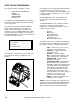
HOW TO USE THIS MANUAL This manual contains the following sections: - HOW TO USE THIS MANUAL SAFETY OPERATIONS MAINTENANCE PARTS LIST The HOW TO USE THIS MANUAL section will tell you how to find important information for ordering correct repair parts. Parts may be ordered from authorized Windsor dealers. When placing an order for parts, the machine model and machine serial number are important. Refer to the MACHINE DATA box which is filled out during the installation of your machine.
IMPORTANT SAFETY INSTRUCTIONS When using an battery powered appliance, basic precaution must always be followed, including the following: READ ALL INSTRUCTIONS BEFORE USING THIS MACHINE. To reduce the risk of fire, electric shock, or injury: Use only indoors. Do not use outdoors or expose to rain. Use only as described in this manual. Use only manufacturer’s recommended components and attachments.
HAZARD INTENSITY LEVEL The following symbols are used throughout this guide as indicated in their descriptions: HAZARD INTENSITY LEVEL There are three levels of hazard intensity identified by signal words -WARNING and CAUTION and FOR SAFETY. The level of hazard intensity is determined by the following definitions: WARNING - Hazards or unsafe practices which COULD result in severe personal injury or death.
SAFETY LABEL LOCATION NOTE: These drawings indicate the location of safety labels on the machine. If at any time the labels become illegible, promptly replace them. 86244310 PRV NO. 500956 CAUTION LABEL 86243830 (2) PRV NO. 500663 PINCH CAUTION 86252520 PRV NO.
TECHNICAL SPECIFICATIONS ITEM Nominal power Rated Voltage Rated Amperage Batteries Battery Compartment Dimensions Propelling Motor Mass (GVW) Weight empty without batteries Tires Maximum Speed Frame Construction Brake Minimum aisle u-turn width Maximum rated climb and descent angle 3-1 DIMENSION/CAPACITY 3450 W 36 Volts DC 95 amps 3 X12 Volt 195-215 AH @ 20 hr. rate 21 in. x 16 in. x 17 in. tall (533mm x 406mm x 432mm) .
TECHNICAL SPECIFICATIONS ITEM Height Length Width Width of Burnishing Path MEASURE 50.6 inches (1285 mm) 52.5 inches (1330 mm) 26.5 inches (670 mm) 20 inches (508mm) WIDTH LENGTH HEIGHT SPECIAL NOTES: The sound pressure level at the operator’s ear was measured to be 64 dBA. This was a nearfield, broadband measurement taken in a typical industrial environment on a tile floor. This appliance contains no possible source of impact noise. The instantaneous sound pressure level is below 63 Pa.
HOW THIS MACHINE WORKS The Chariot is a battery powered, self propelled, hard floor burnisher intended for commercial use. The appliance spins a high-speed burnishing pad in contact with the floor surface to produce a high luster shine. The machines primary systems are the burnishing system, the dust control system and the operator control system. The function of the burnishing system is to spin a high-speed burnishing pad in contact with a floor surface that has had a burnishable floor finish applied.
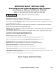
COMPONENTS 2 1 6 5 8 4 3 7 1. 2. 3. 4. Control Panel-Drive Control Panel-Burnish Control Housing Pedal Platform 5. 6. 7. 8.
DRIVE CONTROLS 10 2 8 6 3 7 1 11 9 5 3-5 4 86306300 CHARIOT BURNISHER 11/09/07
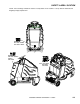
DRIVE CONTROLS 1. 2. 3. 4. 5. 6. 1. Key Switch Emergency Stop/Brake Switch Directional Control Switch Throttle Pedal Operator Presence Pedal - Prior to Serial Number (4*) Speed Control Switch 7. 8. 9. 10. 11. Drive Reset Switch Horn Button Steering Wheel Battery Discharge Indicator Hour Meter KEY SWITCH Controls the power for machine functions. To turn the machine power on, rotate key clockwise. To turn the machine off, rotate key counterclockwise. 2.
DRIVE CONTROLS 6. SPEED CONTROL SWITCH Controls the maximum speed of the machine. There are two setting intended for scrubbing, speeds 1 and 2. Speed 3 is recommended for transport only, not scrubbing. To increase speed, press the top of the switch. To decrease speed, press bottom of the switch. Speeds can be adjusted at any time, whether machine is moving or not. Basic: The position of the switch indicates speed setting. Deluxe: The display indicates speed setting.
DRIVE CONTROLS 10. BATTERY CHARGE LEVEL INDICATOR-BASIC Indicates the charge level of the batteries. The meter display is divided into 10 vertical bars. Bars illuminated on the far right indicate full charge. Bars flashing near the left side indicate the batteries should be recharged. Further operation of the machine could damage the machine or the batteries. If the batteries are not fully recharged, the meter will continue to flash on the left side. 11.
BURNISHER CONTROLS 1 2 3 1. Pad Adjustment Knob 2. Burnisher Head Switch 3.
BURNISHER CONTROLS 1. PAD ADJUSTMENT KNOB Rotate knob to adjust pad pressure. 2. BURNISHER HEAD SWITCH Raises/lowers burnisher head. To lower head, press the bottom of the switch. To raise head, press the top lf the switch. The motor will run only when the head is down and the machine is propelling. 3. PAD PRESSURE METER Indicates relative pad pressure. “Blue area” indicates proper pad pressure range.
MACHINE OPERATION PRE-RUN MACHINE INSPECTION OPERATING THE MACHINE Do a pre-run inspection to find possible problems that could cause poor performance or lost time from breakdown. Follow the same procedure each time to avoid missing steps. 1. Lower or raise deck by pressing burnishing head switch. NOTE: See maintenance section for pre-run machine inspection checklist items. STARTING MACHINE NOTE: Perform pre-run machine check before operating machine.
MACHINE OPERATION TO BEGIN BURNISHING NORMAL BURNISHING When operating the machine around people, pay close attention for unexpected movement. Use extra caution around children. Plan the burnishing patern in advance. The longest track is around the perimeter of the area to be burnished. For efficient operation, the runs should be the longest possible without turning, stopping, or raising or lowering the burnisher head. 1. Stand on the operator platform. Throttle pedal must be in neutral position.
MAINTENANCE SERVICE SCHEDULE BEFORE EACH WORK PERIOD MAINTENANCE Check water level of batteries after charging; add distilled water if necessary. Visually check for damaged or worn tires. Check pad for proper installation. Check dust vacuum hose connections. Check pedal(s), brake and steering for proper operation. Check dust bag. Charge batteries. Clean off top of batteries. Check battery cells with hydrometer. Check battery connections are tight. Clean battery cases and battery compartment.
MAINTENANCE-BATTERIES 1 2 3 4 5 6 1. 2. 3. Rear Cover Retainer Knob Rear Cover Battery Connector-Machine 4. 5. 6.
MAINTENANCE-BATTERIES When servicing machine, avoid contact with battery acid. BATTERIES The batteries provide the power to operate the machine. The batteries require regular maintenance to keep them operating at peak efficiency. The machine batteries will hold their charge for long periods of time, but they can only be charged a certain number of times. To get the greatest life from the batteries, charge them when their charge level reaches 25% of a full charge. Use a hydrometer to check the charge level.
MAINTENANCE-BATTERIES CHECKING BATTERY SPECIFIC GRAVITY CHARGING BATTERIES Use a hydrometer to check the battery specific gravity. When servicing machine, avoid contact with battery acid. Batteries emit hydrogen gas. Explosion or fire can result. Keep sparks and open flame away. Keep covers open when charging. Battery Check Wear eye protection and protective clothing when working with batteries. Charge batteries in a well ventilated area. CHECKING GRAVITY A. Hydrometer B.
MAINTENANCE-BATTERIES CHANGING BATTERIES 5. Replace the battery caps, and leave them in place while charging. Stop the machine in a clean area next to the charger. Turn off machine. 6. Unplug the battery connector from the machine. FOR SAFETY: When charging, connect the charger to the batteries before connecting the charger to the AC wall outlet. Never connect the charger to the AC wall outlet first. Hazardous sparks may result. 7. Plug the charger connector into the battery connector.
MAINTENANCE 1 3 2 1. 2. 3.
MAINTENANCE DUST BAG REPLACEMENT PAD INSTALLATION 1. Raise cover to expose filter cover. Install pad using the pad centering tool (86064370 – PRV NO. 66829). 2. Using lifting access hole, lift bag cover. 3. Carefully remove bag from hose. 4. Slide a new bag onto hose. Ensure bag is pushed on so that top of bag rest on top lip of filter cover. 1. Lay the pad in the pan and position under the pad driver. The edges of the pan will align the pad and driver. 2.
MAINTENANCE-PAD DRIVER PAD DRIVER REPLACEMENT Turn key switch on to lower deck down. Make sure pad adjustment knob is turned fully in the up position (-) counter clockwise. Use needle nose vise grips to clamp together spring retainer bars between spring. Remove the four bolts holding deck assembly onto frame. Two bolts on each side. Label and remove wires coming off of motor. Disconnect by unplugging motor wire harness from machine wire harness. Take note cable tie locations.
MAINTENANCE-PAD DRIVER Use Gear puller to remove pad driver from motor shaft. Take care not to misplace motor shaft key. Install new pad driver, motor shaft key, spacer, washer and bolt. Then install pad lock keeper, pad and pad lock. Turn deck assembly over onto pad 3 7/8 Reattach wires to motor and connect motor wire harness to frame harness. Tie wires in place. Set actuator barrel by rotating barrel up or down to set barrel at 3 -7/8 +0 -3/16 from top of frame to bottom of barrel.
MAINTENANCE-SHUNT ADJUSTMENT SHUNT ADJUSTMENT This pad pressure meter adjustment is factory set. Over the course of time it may become necessary to adjust this setting using the slotted connection on the shunt. GREEN Check the amp range when nuisance tripping of the pad motor controller indicates that the shunt may be out of adjustment. 0 60 GREEN RED APPROX. AMP RANGE 1. Connect a DC ampere meter to the positive battery lead.
MAINTENANCE-DRIVE MOTOR & BRAKE 1. 2. 3.
MAINTENANCE-DRIVE MOTOR & BRAKE ELECTRIC PARKING BRAKE ENGAGEMENT To disengage brake: FOR SAFETY: Before leaving or servicing machine, stop on a level surface, turn off machine and remove key. Electric Brake Engagement This machine is equipped with an electric parking brake. The brake automatically engages and keeps the machine from moving whenever the operator steps off the platform or when emergency stop is engaged.
MAINTENANCE-DRIVE MOTOR & BRAKE DRIVE MOTOR CARBON BRUSH REPLACEMENT Do not use a pressure washer to clean around the motors. Use tap pressure only. FOR SAFETY: Before leaving or servicing machine, stop on a level surface, turn off machine and remove key. 7. Install new brush and reinstall connecting screw and lead. 8. When all new brushes are installed. Place all in retracted position, held into brush holder by spring tension. 9. Carefully replace brush cap. Reinstalling: 1.
MAINTENANCE-CIRCUIT PROTECTION 2 1 1. CIRCUIT BREAKERS Circuit breakers interrupt the flow of power in the event of an electrical overload. When a circuit breaker is tripped, reset it by pressing the exposed button. If a circuit breaker continues to trip, the cause of the electrical overload should be found and corrected. 30 Amp. Protects the propel motor. 2. FUSE The fuse is a one-time circuit protection device designed to stop the flow of electrical current in the event of an electrical overload.
TROUBLESHOOTING PROBLEM No power to machine Little or no propel CAUSE Battery disconnected SOLUTION Check all battery cable connections Emergency shut-off activated Reset Battery cables corroded Faulty key switch Clean connections Replace switch Low battery charge Charge batteries Machine turned on with pedal not in neutral position Tripped circuit breaker Controller overheated Loose motor connection Allow pedal to return to neutral.
MACHINE TROUBLESHOOTINGCONTROLLER FAULT CODES PROPEL CIRCUIT BOARD TROUBLESHOOTING Curtis 1228 LED DIAGNOSTICS- Basic and Cylindrical During normal operation, with no faults present, the status LED is steadily on. If the controller detects a fault, the status LED provides two types of information. First, it displays a slow flash (2 Hz) or a fast flash (4 Hz) to indicate the severity of the fault. Slow-flash faults are self-clearing; as soon as the fault is corrected, the vehicle will operate normally.
MACHINE TROUBLESHOOTINGCONTROLLER FAULT CODES LED CODE 3,1 PROGRAMMER LCD DISPLAY PROC/WIRING FAULT EXPLANATION POSSIBLE CAUSE HPD fault present for >10 sec. 1. Misadjusted throttle. 2. Broken throttle pot or throttle mechanism. 3,2 BRAKE ON FAULT brake On fault 1. Electromagnetic brake driver shorted. 2. Electromagnetic brake coil open. 3,3 PRECHARGE FAULT precharge fault 1. Low battery voltage. 2. KSI and throttle turned on at same time. 3,4 BRAKE OFF FAULT brake Off fault 1.
BURNISHER PARTS 86306300 CHARIOT BURNISHER 11/09/07
BUMPER 10 1 2 7 6 6 8 7 10 9 11 3 5 1 4 5-1 86306300 CHARIOT BURNISHER 11/09/07
BUMPER REF PART NO. PRV NO. QTY DESCRIPTION 1 2 3 4 5 6 7 8 9 10 11 86276890 86007070 86063230 86063240 86071020 86270830 86010670 86070730 86197040 86279130 86251750 70752 70849 140813 140814 140783 57023 87029 140729 57264 87083 67602 6 2 1 1 1 4 4 2 4 4 2 SCR, 5/16-18X3/4 PTHMS SS SCR, #12 X 1.
CONTROL PANEL 22 29 2 21 31 34A 34B 45 47 44 20 23 24 5 6 27 7 19 26 25 35 8 32 18 33 9 16 11 10 36 37 38 15 34 39 16 12 13 40 41 17 46 45 42 28 14 44 43 17 17 30 17 5-3 4 3 1 86306300 CHARIOT BURNISHER 11/09/07
CONTROL PANEL REF PART NO. PRV NO.
CONTROLS & HOUSING 14 23 12 22 15 1 DETAIL 'A' 2 2 10 4 20 3 7 5 21 19 18 SEE DETAIL 'A' 13 17 16 6 24 12 11 9 10 5-5 86306300 CHARIOT BURNISHER 12/22/08
CONTROLS & HOUSING REF PART NO. PRV NO.
DECALS 6 4 5 3 2 1 7 5-7 86306300 CHARIOT BURNISHER 01/06/09
DECALS REF PART NO. PRV NO. QTY DESCRIPTION 1 2 3 4 5 6 7 86004970 86244760 86244770 86244190 86244290 86243990 86244350 50990 501224 501225 500882 500943 500780 501050 1 1 1 1 1 1 1 LABEL, WINDSOR LOGO DOMED DECAL, CHARIOT SIDE IGLOSS RT DECAL, CHARIOT, SIDE IGLOSS LT LABEL, PANEL BASIC LEFT LABEL, PANEL DECAL , RH LABEL, COVER PANEL LABEL, PAD ALIGNMENT SERIAL NO. FROM NOTES: NOTE: See “SAFETY LABEL LOCATION” page for safety label information.
FILTER 14 5 10 12 2 3 10 4 6 8 13 9 1 7 1 1 11 1 7 5-9 86306300 CHARIOT BURNISHER 11/09/07
FILTER REF PART NO. PRV NO. QTY 1 2 3 4 5 6 7 8 9 10 11 12 13 14 86006590 86270320 86002840 86072500 86002380 86079280 86270970 86276890 86079250 86270990 86271820 86063790 86072510 86284870 70088 39729 27282 14398 20046 620094 57081 70752 620091 57090 57270 27880 14399 2003SM 6 1 1 1 1 1 5 2 1 4 2 1 1 - DESCRIPTION SERIAL NO. FROM NOTES: SCR, 10-32 X 1/2 PPHMS SS HOSE ASM, 1.5 BLK VAC X 36 CUFF, 1.5 SLIP X 1.5 HOSE BRKT, FILTER COVER LATCH CLAMP, 2.
FRAME-LOWER 14 16 17 15 12 13 1 3 11 2 4 3 3 3 8 9 5 3 10 9 3 9 6 21 3 7 24 18 22 23 19 20 27 25 6 26 3 5-11 86306300 CHARIOT BURNISHER 11/09/07
FRAME-LOWER REF PART NO. PRV NO.
FRAME-UPPER 1 2 3 2 3 2 4 4 5 7 9 2 2 3 4 2 3 6 8 4 4 3 5-13 86306300 CHARIOT BURNISHER 11/09/07
FRAME-UPPER REF PART NO. PRV NO. QTY DESCRIPTION 1 2 3 4 5 6 7 8 9 86071360 86270830 86010670 86276070 86292100 86074160 86073500 86277460 86238450 140855 57023 87029 70593 270101 270090 70847 36245 1 10 9 9 1 1 1 2 1 BRKT, HORIZ ELECT, BURNISHER NUT, 5/16-18 HEX NYLOCK SS WASHER, 5/16 FLAT SS SCR, 5/16-18 X 3/4 CARRIAGE SS PLATE VERTICAL SUPPORT CHANNEL, RIGHT DELUXE BRKT, SIDE CHANNEL L SCR, 5/16-18 X 5/8 BSHCS SS GROMMET, 3.0 ID X 3.25 GROOVE 86306300 CHARIOT BURNISHER 11/09/07 SERIAL NO.
HOOD 12 10 11 7 6 5 13 6 8 9 5 15 1 16 4 3 14 16 1 5-15 86306300 CHARIOT BURNISHER 12/22/08
HOOD REF PART NO. PRV NO.
PEDAL PLATFORM-From Serial Number (4*) 21 18 8 16 19 9 17 25 2 1 22 15 30 6 14 3 4 24 10 22 5 29 15 12 26 28 13 11 23 27 20 7 5-17A 86306300 CHARIOT BURNISHER 03/31/10 11
PEDAL PLATFORM-From Serial Number (4*) REF PART NO. PRV NO.
PEDAL PLATFORM-To Serial Number (4*) 1 2 9 30 28 3 10 4 11 12 5 6 31 8 9 23 22 27 26 25 10 13 7 11 12 15 24 20 29 14 17 16 17 32 18 19 21 20 17 5-18A 86306300 CHARIOT BURNISHER 11/18/09
PEDAL PLATFORM-To Serial Number (4*) REF PART NO. PRV NO.
PEDAL PLATFORM 2 3 13 15 6 11 6 14 12 10 9 7 1 4 8 5 8 5 5-19 86306300 CHARIOT BURNISHER 11/18/09
PEDAL PLATFORM REF PART NO. PRV NO. QTY 1 2 3 4 5 6 7 8 9 10 11 12 13 14 15 86008680 86274690 86264920 86231070 86010670 86259430 86010770 86270830 86211280 86278850 86248920 86249560 86271190 86007780 86259440 80607 70258 27049 730328 87029 87485 87143 57023 70852 80613 66487 629993 57142 73576 87486 1 2 3 2 5 4 2 4 2 2 1 1 2 1 2 DESCRIPTION SERIAL NO. FROM NOTES: COTTER, 1/2” RING SCR, 5/16-18 X 1.5 HHCS GR5PLT CABLE TIE, 7” UL/CSA BUMPER, 1 X 1.
REAR COVER 21 23 18 20 22 18 14 13 1 10 2 3 9 19 18 3 2 11 12 15 16 9 8 7 6 17 5 4 5-21 86306300 CHARIOT BURNISHER 04/16/09
REAR COVER REF PART NO. PRV NO.
DECK LIFT MECHANISM 43 4 1 2 37 10 6 7 3 10 36 8 5 7 9 11 10 11 12 39 10 42 12 39 10 14 15 SEE DETAIL 'A' 13 16 34 38 14 35 34 17 18 19 29 31 28 20 30 27 32 26 25 24 33 21 23 22 DETAIL 'A' 40 41 5-23 86306300 CHARIOT BURNISHER 01/17/09
DECK LIFT MECHANISM REF PART NO. PRV NO. QTY DESCRIPTION 1 2 3 4 5 6 7 8 9 10 11 12 13 14 15 86271840 86279130 86135970 86028170 86277030 86006560 86010670 86231090 86071480 86270830 86228840 86259400 86083510 86277130 86073440 57285 87083 48045 53269 70780 70083 87029 80809 140868 57023 09124 87205 66834 70795 149992 3 3 1 1 4 2 4 2 1 14 8 8 1 8 1 NUT, 5/16-18 HEX NYLOCK THIN SS WASHER, 5/16 SPLIT LOCK PLTD KEY, 3/16 SQ X 5/8 LONG MOTOR, 36VDC 4HP 2000RPM SCR, 5/16-18 X 1.
DECK LIFT LINKAGE 20 21 35 19 34 22 15 23 24 35 33 27 26 18 25 32 17 1 DETAIL 'A' 2 3 16 DETAIL 'B' 4 12 5 6 31 7 9 8 11 28 DETAIL 'B' DETAIL 'A' 11 10 30 29 13 14 15 5-25 86306300 CHARIOT BURNISHER 12/13/08
DECK LIFT LINKAGE REF PART NO. PRV NO.
STEERING 1 2 3 4 5 6 8 7 33 28 32 9 31 10 11 30 12 13 27 26 25 14 15 24 14 19 29 23 20 22 19 21 18 16 17 7 23 5-27 86306300 CHARIOT BURNISHER 11/09/07
STEERING REF PART NO. PRV NO.
WHEEL-FRONT DRIVE-CHAIN 1 2 3 4 9 9 5 20 18 17 33 8 32 9 10 11 12 6 7 31 13 14 30 29 28 15 27 16 17 26 18 17 25 22 1 36 23 24 18 21 14 86306300 CHARIOT BURNISHER 08/25/09 15 19
WHEEL-FRONT DRIVE-CHAIN REF PART NO. PRV NO.
WHEEL-FRONT BRAKE 1 2 3 15 14 10 11 13 12 4 16 7 8 9 5-31 86306300 CHARIOT BURNISHER 08/01/09 6 5
WHEEL-FRONT BRAKE REF 1 2 3 4 5 PART NO. 86010790 86275190 86006170 86005810 86318830 PRV NO. 87163 70377 66031 57245 - QTY 4 4 1 2 1 6 86233410 81270 1 7 86005710 57105 4 8 86273740 70010 2 9 86008920 80889 2 10 11 12 13 14 15 16 86257490 86006840 86010630 86273340 86001740 86264930 86320870 76155 70390 87013 00-000289 140816 27050 - 2 2 2 4 1 1 1 DESCRIPTION WASHER, 3/8 SPLIT LOCK PLTD SCR, 3/8-16 X 1.
WHEEL-FRONT DRIVE, GEAR 1 2 5 6 7 3 8 4 9 21 20 19 11 10A 10B 12 13 14 16 18 5-33 15 17 86306300 CHARIOT BURNISHER 02/21/09 22
WHEEL-FRONT DRIVE, GEAR REF 1 2 3 4 5 6 7 8 9 10A 10B 11 12 13 14 15 16 17 18 19 20 21 PART NO. 86275190 86010790 86002830 86006170 86223980 86219420 86223480 86224020 86317190 86011120 86259920 86224440 86222720 86225810 86279710 86136640 86222770 86279690 86277340 86223980 86318830 86222760 PRV NO. 70377 87163 27196 66031 09134 41510 67450 730233 89262 89273 730387 620037 87506 87245 70262 620042 87243 70830 09134 620041 QTY 4 4 1 1 3 1 2 1 1 1 1 1 1 1 1 1 1 4 4 3 10 1 DESCRIPTION SCR, 3/8-16 X 1.
WHEEL-REAR 1 4 3 2 5-35 86306300 CHARIOT BURNISHER 04/11/09
WHEEL-REAR REF PART NO. PRV NO. QTY DESCRIPTION 1 2 3 4 86259950 86008710 86232130 86322590 89276 80623 17309 - 2 2 2 2 WHEEL, 10X2.5 W/BRNGS, GRY, NT RING, ¾” EXT SNAP H-D CAP, 2.75 ID X 1.0 L BLK VINYL WHEEL, 10X2.5 W/BRNGS, GRY, NT SERIAL NO.
WIRING-BATTERIES 2 3 4 1 20A 20B 5 9 24 25 23 7 6 10 11 8 26 1 22 13 14 15 16 19 17 18 5-37 86306300 CHARIOT BURNISHER 11/09/07
WIRING-BATTERIES REF PART NO. PRV NO.
WIRING-COMPONENTS 2 1 3 4 6 4 5 7 8 9 10 11 13 12 5-39 86306300 CHARIOT BURNISHER 02/03/09
WIRING-COMPONENTS REF PART NO. PRV NO. QTY DESCRIPTION 1 2 3 4 5 6 7 8 9 10 11 12 13 86273830 86010780 86255910 86005710 86006850 86005710 86010630 86008920 86238500 86276070 86233410 86270830 86239720 70020 87162 73659 57105 70393 57105 87013 80889 81427 70593 81270 57023 41520 2 2 2 2 2 2 3 2 2 1 1 1 1 SCR, 1/4-20 X 1/2 HHCS SS WASHER, 1/4 SPLIT LOCK PLTD STANDOFF, 1/4-20 X 1.0 HEX INS NUT, 1/4-20 HEX W/STAR WASHER SET SCR, 1/4-20 X 1.
WIRING-CONTROL PANEL 45 BLK 44 RED TO BURNISHER RELAY 41 RED 46 BLK 12 ORG TO SHUNT B C D E 2 BLK 1 WHT 55 RED 40 RED 30A 56 RED 3A 39 RED 11 ORG 35 RED 59 RED 3 LT BLU G 4 28 GRN 27 YLW 26 YLW 29 GRN 30 GRN 54 ORG 53 LT BLU 52 BLK 19 BLK 46 BLK 49 WHT 20 WHT 48 WHT 47 RED 8 BRN 9 BRN 32 BLU 25 BLK 23 BLK 16 LT BLU 23 RED 23 RED 22 RED 51 WHT/RED REMOVABLE JUMPER 17 WHT/YLW 61 BLK 42 RED 31 GRY 33 25 BLK 50 RED 36 RED J 57 BLK 13 BLK 63 BLK 58 BLK 24 BLK 45 BLK 65 BLK
WIRING-CONTROL PANEL REF PART NO. PRV NO. QTY DESCRIPTION 1 2 3 4 5 6 7 8 86239180 86261250 86010860 86261210 86237000 86260560 86251490 86311210 41537 29273 880353 29204 80688 880428 67619 - 1 1 1 2 1 1 1 1 HARNESS, CONTROL PANEL BRSHR DIODE ASM, FAST RECOVERY WIRE, 4X20 BK CTERM X 5/16 RING DIODE ASM, 76008 X 76008 FUSE, 80 AMP WIRE, 4X10RD 5/16RING X 5/16RING RESISTOR ASM, 1/2 WATT 33 OHM LIGHT ASM, INDICATOR, CODE 86306300 CHARIOT BURNISHER 05/27/08 SERIAL NO.
WIRING-DRIVE MOTOR RED BLK 1 WHT 2 BLK 1 2 BLK 1 WHT 2 BLK WHT BLK CONTROL PANEL HARNESS 5-43 86306300 CHARIOT BURNISHER 11/09/07
WIRING-DRIVE MOTOR 120 REF 1 PART NO. PRV NO. QTY DESCRIPTION 86239120 41522 1 HARNESS, CHARIOT PROPEL 86306300 CHARIOT BURNISHER 11/09/07 SERIAL NO.
WIRING-MAIN HARNESS DIAGRAM A 64 65 RE BL D K HORN 12 ORG 12 ORG 17 WHT/YLW 19 BLK 8 BRN 13 BLK 20 WHT BRAKE 13 BLK 16 BLU 20 WHT 7 BRN 19 BLK DRIVE MOTOR 7 BRN 8 BRN 1 21 DK BLU SWITCH BRUSH MOTOR (BASIC ONLY) DIAGRAM B 22 DK BLU 8 1 18 WHT/BLU 51 WHT/RED 15 WHT/RED 16 LT BLU 21 DK BLU 50 RED 54 ORG 17 WHT/YLW DECK LIFT ACTUATOR 5 4 2 3 BURINSHER MOTOR FAN 24 BLK 25 RED 24 BLK D 25 RED U V W 4 9 BLK 10 BLK 11 BLK U 5 E 9 8 W V 7 GRN DIAGRAM C 65 RED 4 3 63 BLU 60 RED
WIRING-MAIN HARNESS REF 1 2 3 4 5 6 7 8 9 PART NO. PRV NO. QTY 86239170 86239190 86239520 86260220 86009000 86260600 86010860 86260580 86261210 41528 41538 880446 80875 81131 880445 880353 880443 29204 1 1 1 3 1 1 1 1 1 DESCRIPTION SERIAL NO. FROM NOTES: HARNESS, BRAKE HARNESS, MAIN BRSHR HARNESS, HALL SENSOR WIRE4X30BK 5/16RINGX5/16RING WIRE4X9.
WIRING-PEDAL PLATFORM-From Serial Number (4*) B A 1 8 BLU 9 RED DIAGRAM A DIAGRAM B ORG BRN GRN GRN BRN ORG LT BLU RED 5-47A 86306300 CHARIOT BURNISHER 11/18/09
WIRING-PEDAL PLATFORM-From Serial Number (4*) REF PART NO. PRV NO. QTY 1 86315100 - 1 DESCRIPTION SERIAL NO. FROM NOTES: HARNESS, PEDAL *SEE SERIAL NUMBER PAGE.
WIRING-PEDAL PLATFORM-To Serial Number (4*) B A 1 BRN BLU BRN RED DIAGRAM A DIAGRAM B ORG BRN GRN 5 GRN 1 2 3 7 BRN 4 5 6 ORG LT BLU RED 5-48A 86306300 CHARIOT BURNISHER 11/18/09
WIRING-PEDAL PLATFORM-To Serial Number (4*) REF PART NO. PRV NO. QTY DESCRIPTION 1 86218810 23717 1 HARNESS, TWISTER PEDAL SERIAL NO. FROM NOTES: *SEE SERIAL NUMBER PAGE.
5-49 BLK M1 WHT M2 36/RED 37/RED 56/RED 86311210 58/BLK 2 86260580 PRV NO. 880443 86237000 PRV NO. 80688 9/BRN 3 42/RED B- B+ 86261250 PRV NO. 29273 38/RED 43/BLK 44 RED 86010860 PRV NO. 880353 STATUS LED 86260570 PRV NO. 880429 86306300 CHARIOT BURNISHER 12/22/08 31/GRY 1 52/BLK 48/WHT 47/RED 49/WHT 22/RED WHT 59/RED 86261210 PRV NO. 29204 44/RED 28/GRN 29/GRN 100K 30/GRN 200K 61/BLK 86251490 PRV NO.
SUGGESTED SPARE PARTS PART NO. PRV NO. DESCRIPTION 86284870 86001910 86002000 86002010 86004870 86248280 86251410 86007140 86007170 86007190 86007240 86237000 86001740 86002730 86216230 86026450 2003SM 14606 14717 14942 48077 64110 67506 72130 72159 72161 72190 80688 140816 270085 730074 730352 SM FILTER BAG PACKS 10/PKG BREAKER, 30A 50VDC CIRCUIT BREAKER, 3 AMP BOOT, 3/8 CIRCUIT BREAKER KNOB, 3.50 OD X 3/8-16 PAD DRIVER ASSEMBLY 20”, .
BACK-UP ALARM - OPTION 3 1 2 4 5-51 86306300 CHARIOT BURNISHER 11/09/07
BACK-UP ALARM - OPTION REF PART NO. PRV NO. QTY 1 2 3 4 86071140 86231500 86276780 86271840 140817 80882 70728 57285 1 1 1 1 DESCRIPTION SERIAL NO.
BATTERY CART - OPTION 27 26 28 3 30 5 24 3 8 9 29 25 2 6 1 2 15 3 4 3 23 3 22 5 10 5 3 3 6 9 8 7 13 12 5 3 14 20 11 21 19 16 15 18 17 5-53 31 3 86306300 CHARIOT BURNISHER 09/17/09 3
BATTERY CART - OPTION REF 1 2 3 4 5 6 7 8 9 10 11 12 13 14 15 16 17 18 19 20 21 22 23 24 25 26 27 28 29 30 31 PART NO. 86006930 86254290 86270830 86077010 86010670 86228840 86259410 86259400 86254890 86068490 86231090 86083120 86076600 86004070 86276790 86276690 86199430 86078890 86277130 86007020 86232590 86001350 86011020 86271840 86008130 86274730 86070790 86087340 86070800 86271870 86276070 PRV NO.
BATTERY CART - OPTION 1 2 4 5 3 7 7 5 6 10 3 6 17 3 8 9 10 11 12 13 14 15 6 10 10 3 3 16 5-55 86306300 CHARIOT BURNISHER 11/09/07
BATTERY CART - OPTION REF PART NO. PRV NO.
SEAT - OPTION 2 13 14 1 12 11 3 4 5 6 10 9 8 7 15 16 17 18 19 20 23 24 22 21 5-57 86306300 CHARIOT BURNISHER 11/09/07
SEAT - OPTION REF PART NO. PRV NO.
WARNING LIGHTS - OPTION 1 6 2 3 3 4 FRONT 5 7 3 1 2 6 5-59 REAR 86306300 CHARIOT BURNISHER 11/09/07
WARNING LIGHTS - OPTION REF PART NO. PRV NO. QTY 1 2 3 4 5 6 7 86270990 86010650 86276820 86071490 86270990 86246200 86071500 57090 87018 70740 140871 57090 51454 140872 4 4 4 1 2 2 1 DESCRIPTION SERIAL NO.
5-61 5-97 86306300 CHARIOT BURNISHER 11/09/07
SERIAL NUMBERS REF. NO.