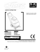
CARPET EXTRACTOR Operating Instructions (USA) Bedienungsanleitung (GER) MODEL: CDT7IA/10080050 CDT7IB/10080060 CDT7IE/10080070 CDT7IS/10080080 COUNTRY AUSTRALIA BRITIAN EUROPE SWITZERLAND IPX4 Read instructions before operating the machine Bitte lesen Sie diese Anleitungen, bevor Sie die Maschine in Gebrauch nehmen AF 86038340 04/19/07 PRV NO.
MACHINE DATA LOG/OVERVIEW MODEL _______________________________________ DATE OF PURCHASE __________________________ SERIAL NUMBER ______________________________ SALES REPRESENTATIVE # _____________________ DEALER NAME ________________________________ OPERATIONS GUIDE NUMBER ___________________ PUBLISHED __________________________________________ Copyright 2002 Windsor Industries, Printed in USA YOUR DEALER Name: _____________________________________________________________________________________________
TABLE OF CONTENTS Machine Data Log/Overview (English). ........1 Machine Data Log/Overview (German). .......2 Table of Contents (English) ..........................3 Table of Contents (German) .........................4 HOW TO USE THIS MANUAL How to use this Manual. ........................1-1ENG SAFETY GROUP PARTS LIST Frame Assembly..........................................5-1 Brush Assembly...........................................5-3 Pump Assembly...........................................
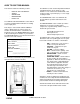
HOW TO USE THIS MANUAL This manual contains the following sections: - - HOW TO USE THIS MANUAL SAFETY OPERATIONS MAINTENANCE PARTS LIST The HOW TO USE THIS MANUAL section will tell you how to find important information for ordering correct repair parts. Parts may be ordered from authorized Windsor dealers. When placing an order for parts, the machine model and machine serial number are important. Refer to the MACHINE DATA box which is filled out during the installation of your machine.
IMPORTANT SAFETY INSTRUCTIONS When using an electrical appliance, basic precaution must always be followed, including the following: READ ALL INSTRUCTIONS BEFORE USING THIS MACHINE. This machine is for commercial use. ! WARNING: To reduce the risk of fire, electric shock, or injury: Connect to a properly grounded outlet. See Grounding Instructions. Do not leave the machine unattended. Unplug machine from outlet when not in use and before maintenance or service. Use only indoors.
HAZARD INTENSITY LEVEL The following symbols are used throughout this guide as indicated in their descriptions: HAZARD INTENSITY LEVEL There are three levels of hazard intensity identified by signal words -WARNING and CAUTION and FOR SAFETY. The level of hazard intensity is determined by the following definitions: ! WARNING WARNING - Hazards or unsafe practices which COULD result in severe personal injury or death.
SAFETY LABEL LOCATION NOTE: These drawings indicate the location of safety labels on the CDT7//10080230. If, at any time, the labels become illegible contact your Windsor representative for prompt replacement. WARNING DECAL 86242230 PRV NO.
ACCESSORY TOOL USAGE STEP 1 Use only one of the following acceptable accessory tools. 86000000 – PRV NO. DDH 86031540 – PRV NO. 39504 86041180 – PRV NO. ESW 86000050 – PRV NO. SPW 86000020 – PRV NO. HT Pull back collar and insert over machine mounted fitting, then release collar to lock into place. STEP 2 PUMP VACUUM ON STEP 3 ON Lift door on front of vacuum shoe and insert 1 ½ inch hose cuff into hole. Turn on Pump and Vacuum Switch.
TECHNICAL SPECIFICATIONS POWER TYPE GENERAL DIMENSIONS/WEIGHT ELECTRICAL: 230-240 V, 7 A, 50 HZ Vacuum shoe: 17” (43.18 cm) cast aluminum with spring loaded down pressure ELECTRIC VACUUM MOTOR: (1) –3 stage, 1 hp, 99 cfm (2.80 cubic meters/min.) Waterlift –117” (297cm) WHEELS: (2) 10” dia. (25 cm) wheels by 2” BRUSH: (1) 15” (38.1 cm.) SOLUTION PUMP: 100 PSI, diaphragm style, internal bypass WEIGHT: 92lbs. (42kg) LENGTH: 41” (104 cm) SOLUTION CAPACITY: 7 gallons (26.5ltr) HEIGHT: 34” (86.
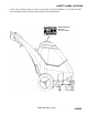
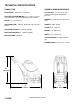
CONTROLS/COMPONENT LOCATIONS 3 5 4 1 1. Main Handle. Used to pull and maneuver machine. 2. Electrical Cord. 3. Pump Switch. Turns on pump and enables spray. 4. Brush/Spray switch. Turns on brush motor and activates electro-valve to dispense solution to floor through jets. Intermittent, off, and continuous settings. 5. Vacuum Motor Switch. Turns on vacuum motor 6. Brush Motor Circuit Breaker. 4 amp. Breaker protecting brush motor. 7. Vacuum Motor Circuit Breaker. 7 amp.
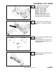
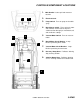
CONTROLS/COMPONENT LOCATIONS 1. Solution Accessory Tool Hookup. Used for various auxiliary cleaning tools. 2. Vacuum Hose Door. Used to connect various auxiliary 1-1/2 inch cleaning tool vacuum hoses. 3. Brush Height Adjustment. Used to regulate brush height from storage position to various carpet heights. 4. Recovery Tank. Used to collect dirty cleaning solution. 5. Solution Tank. Used to hold cleaning solution. 6. Recovery Tank Dome. 7. Vacuum Shoe. 8. Brush Housing. 9.
CONTROLS/COMPONENT LOCATIONS 1. Solution Intake Cover. 2. Vacuum Intake Cover. 3. Float Shut-Off. 4. Clean-Out Opening. 5. Pour Spout. 6. Lift Handle.
FILLING OPERATIONS STEP 1 RECOVERY TANK Remove recovery tank SOLUTION TANK STEP 2 FILL LINE Add water 7 gal. (26.5 ltr.) 140°F (60°C) STEP 3 FILLING THE CADET NOTE: Use clean bucket of water to fill solution tank Do not put defoamer, solvents, spotter or prespray chemicals in the solution tank. 7 – 14oz. (207ml – 414ml) Add cleaning chemical Do not allow water to spill into vacuum motor inlet. Dry spillage from top of solution tank before replacing recovery tank.
OPERATIONS STEP 1 STEP 2 STEP 3 1/8in (3mm) CORRECT Remove electrical cord and literature from recovery tank. Fill solution tank (see filling operations, page 3-5). Plug cord into grounded outlet. Note: Be sure dome is seated on recovery tank, and float shut-off is installed correctly. Adjust brush to proper setting. Note: For good operation the brush must skim the carpet. If circuit breaker trips raise brush to prevent damage to motor or carpet.
OPERATIONS Tip machine back by main handle to move to starting point. STEP Lower machine to floor. STEP Select intermittent or continuous switch setting to turn on brush and start solution spray. The intermittent setting requires the operator to hold the switch in the “on” position with the thumb, and is typically used in small areas where short cleaning passes are made.
CLEANING PROCEDURE STEP 1 STEP 2 1ft. (30cm) Release intermittent setting or turn off continuous setting on brush/spray switch approximately 1 foot before ending cleaning pass. OFF STEP 1in. (25mm) 3 SOLUTION INTAKE COVER VACUUM INTAKE COVER Start at wall closest to power outlet. Pull straight back without pushing down on handle. STEP 4 Push down on handle to raise vacuum shoe and brush before moving to the next cleaning pass.
CLEANING PROCEDURE Use right side of machine for cleaning against walls. STEP After cleaning, turn off all controls, return brush to storage position and carefully unplug machine. STEP 5 6 OFF OFF OFF To speed drying, use a Windblower™ fan. STEP Empty recovery tank by releasing dump hose. Use a hose with cold water to clean out the recovery tank. Also drain solution tank after each use.
MAINTENANCE PERIODIC MAINTENANCE DAILY / REGULAR MAINTENANCE Twice a month, flush a white vinegar solution (One quart vinegar to two gallons of water) or anti-browning solution (mixed as directed) through the extractor. This will prevent build-up of alkaline residue in the system. If spray jets become clogged, remove the spray tips, wash them thoroughly, and blow-dry. Before making any adjustments or repairs to the machine, disconnect the power cord from electrical source.
MAINTENANCE ONLY QUALIFIED MAINTENANCE PERSONNEL ARE TO PERFORM THE FOLLOWING REPAIRS. Vac Motor Carbon Brushes Replacement (Ametek) End Cap VACUUM MOTOR REPLACEMENT Carbon Brushes ! WARNING: 1. Turn off all switches and unplug machine. 2. Remove recovery tank. 3. Remove the (2) screws that fasten the solution tank to the frame, and tilt tank back to expose the inside of the frame. 4. Locate the vacuum motor wires and disconnect at the connector. Close the solution tank. 5.
MAINTENANCE BELT REPLACEMENT 1. Turn off all switches and unplug machine. 2. Remove recovery tank and brush. 3. Remove the (2) screws that fasten the solution tank to the frame, and tilt tank back to expose the inside of the frame. 6. Remove the (3) screws that fasten the side plate (p/n 86249420 – PRV NO. 62759) to the brush housing to remove belt. NOTE: All components associated with driving the brush will come out with the side plate. 7. Reverse process to install belt. 4.
TROUBLESHOOTING CHART PROBLEM CAUSE SOLUTION 1. Is the cord plugged in. 1. Plug in cord. 2. Circuit breaker tripped in building. 2. Reset breaker 3. Faulty switch. 3. Call for service. 4. Faulty power cord or pigtail. 4. Call for service. Vacuum Motor Will Not 1. Vacuum circuit breaker tripped. 1. Reset breaker Run 2. Faulty main vacuum switch. 2. Call for service. 3. Loose wiring. 3. Call for service. 4. Faulty vac motor. 4. Call for service. Vacuum Motor Runs But 1.
WIRING DIAGRAM 86003650 PRV NO. 34362 86268750 PRV NO. 88567 86268750 PRV NO. 88567 86268900 PRV NO. 88655 86268750 PRV NO. 88567 86004480 PRV NO. 41353 86268900 PRV NO. 88655 4-5ENG CADET 86038340 04/19/07 86268350 PRV NO. 88270 86001240 PRV NO. 14020 86268750 PRV NO.
NOTES CADET 86038340 04/19/07 4-6ENG