CARPET EXTRACTOR Operating Instructions MODEL: CDT7 10080220 Read these instructions before operating the machine UU 86038220 09/27/07 PRV NO.
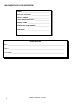
MACHINE DATA LOG/OVERVIEW MODEL _______________________________________ DATE OF PURCHASE __________________________ SERIAL NUMBER ______________________________ SALES REPRESENTATIVE # _____________________ DEALER NAME ________________________________ OPERATIONS GUIDE NUMBER ___________________ PUBLISHED __________________________________________ YOUR DEALER Name: __________________________________________________________________________________________________ Address: __________________________________
TABLE OF CONTENTS Machine Data Log/Overview.........................1 Table of Contents..........................................2 HOW TO USE THIS MANUAL How to use this Manual.................................1-1 SAFETY Important Safety Instructions ........................2-1 Hazard Intensity Level ..................................2-2 Grounding Instructions..................................2-3 OPERATIONS Technical Specifications. ..............................3-1 Controls/Component Location ...........
HOW TO USE THIS MANUAL This manual contains the following sections: - HOW TO USE THIS MANUAL SAFETY OPERATIONS MAINTENANCE PARTS LIST The HOW TO USE THIS MANUAL section will tell you how to find important information for ordering correct repair parts. Parts may be ordered from authorized dealers. When placing an order for parts, the machine model and machine serial number are important. Refer to the MACHINE DATA box which is filled out during the installation of your machine.
SAFETY INSTRUCTIONS IMPORTANT SAFETY INSTRUCTIONS When using an electrical appliance, basic precaution must always be followed, including the following: READ ALL INSTRUCTIONS BEFORE USING THIS MACHINE. This machine is for commercial use. ! WARNING: To reduce the risk of fire, electric shock, or injury: Connect to a properly grounded outlet. See Grounding Instructions. Do not leave the machine unattended. Unplug machine from outlet when not in use and before maintenance or service. Use only indoors.
HAZARD INTENSITY LEVEL The following symbols are used throughout this guide as indicated in their descriptions: HAZARD INTENSITY LEVEL There are three levels of hazard intensity identified by signal words -WARNING and CAUTION and FOR SAFETY. The level of hazard intensity is determined by the following definitions: ! WARNING WARNING - Hazards or unsafe practices which COULD result in severe personal injury or death.
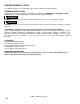
GROUNDING INSTRUCTIONS THIS PRODUCT IS FOR COMMERCIAL USE ONLY. PROPER GROUNDING Grounding Pin ELECTRICAL: In the USA this machine operates on a standard 15 amp 115V, 60 hz, A.C. power circuit . The amp, hertz, and voltage are listed on the data label found on each machine. Using voltages above or below those indicated on the data label will cause serious damage to the motors. Grounded Outlet Fig. A Metal Screw Adaptor Grounded Outlet Box Fig. B Tab For Grounding Screw Adaptor Fig.
TECHNICAL SPECIFICATIONS POWER TYPE GENERAL DIMENSIONS/WEIGHT ELECTRICAL: 115 V, 15 A, 60 HZ Vacuum shoe: 17” (43.18 cm) cast aluminum with spring loaded down pressure ELECTRIC VACUUM MOTOR: (1) –3 stage, 1 hp, 99 cfm (2.80 cubic meters/min.) Waterlift –117” (297cm) BRUSH: (1) 15” (38.1 cm.) WHEELS: (2) 10” dia. (25 cm) wheels by 2” SOLUTION PUMP: Diaphragm style, internal bypass WEIGHT: 92lbs. (42kg) SOLUTION CAPACITY: 7 gallons (26.5ltr) LENGTH: 41” (104 cm) RECOVERY CAPACITY: 7 gallons (26.
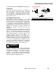
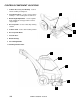
CONTROLS/COMPONENT LOCATIONS 1. Main Handle. Used to pull and maneuver machine. 2. Electrical Cord. 3 3. Pump Switch. Turns on pump and enables spray. 5 4. Brush/Spray switch. Turns on brush motor and activates electro-valve to dispense solution to floor through jets. Intermittent, off, and continuous settings. 5. Vacuum Motor Switch. Turns on vacuum motor 6. Brush Motor Circuit Breaker. 6 amp. Breaker protecting brush motor. 4 1 7. Vacuum Motor Circuit Breaker. 15 amp.
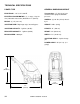
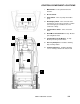
CONTROLS/COMPONENT LOCATIONS 1. Solution Accessory Tool Hookup. Used for various auxiliary cleaning tools. 10 2. Vacuum Hose Door. Used to connect various auxiliary 1 ½ inch cleaning tool vacuum hoses. 3. Brush Height Adjustment. Used to regulate brush height from storage position to various carpet heights. 1 4. Recovery Tank. Used to collect dirty cleaning solution. 5. Solution Tank. Used to hold cleaning solution. 9 6. Recovery Tank Dome. 2 3 7. Vacuum Shoe. 8. Brush Housing. 9.
CONTROLS/COMPONENT LOCATIONS 1. Solution Intake Cover. 2. Vacuum Intake Cover. 3. Float Shut-Off. 4. Clean-Out Opening. 5. Pour Spout. 6. Lift Handle.
FILLING OPERATIONS STEP 1 RECOVERY TANK Remove recovery tank SOLUTION TANK STEP 2 FILL LINE Add water 7 gal. (26.5 ltr.) 140°F (60°C) STEP 3 FILLING THE CADET NOTE: Use clean bucket of water to fill solution tank 7 – 14oz. (207ml – 414ml) Add cleaning chemical Do not put defoamer, solvents, spotter or prespray chemicals in the solution tank. Do not allow water to spill into vacuum motor inlet. Dry spillage from top of solution tank before replacing recovery tank.
OPERATIONS STEP 1 Remove electrical cord and literature from recovery tank. Fill solution tank (see filling operations, page3-5). STEP 2 Plug cord into grounded outlet. Note: Be sure dome is seated on recovery tank, and float shut-off is installed correctly. STEP 3 Adjust brush to proper setting. Note: For good operation the brush must skim the carpet. If circuit breaker trips raise brush to prevent damage to motor or carpet. STEP 4 Turn on both Vacuum and Pump motor switches (“ON”=“I”).
OPERATIONS Tip machine back by main handle to move to starting point. STEP 5 Lower machine to floor. STEP 6 Select intermittent or continuous switch setting to turn on brush and start solution spray. The intermittent setting requires the operator to hold the switch in the “on” position with the thumb, and is typically used in small areas where short cleaning passes are made.
CLEANING PROCEDURE 1ft. (30cm) STEP 1 Start at wall closest to power outlet. Pull straight back without pushing down on handle. STEP 2 Release intermittent setting or turn off continuous setting on brush/spray switch approximately 1 foot before ending cleaning pass. STEP 3 Push down on handle to raise vacuum shoe and brush before moving to the next cleaning pass. Overlap brush contact area approximately 1inch. OFF 1in.
CLEANING PROCEDURE Use right side of machine for cleaning against walls. STEP 5 After cleaning, turn off all controls, return brush to storage position and carefully unplug machine. STEP 6 OFF OFF OFF To speed drying, use a Windblower™ fan. STEP 7 Empty recovery tank by releasing dump hose. Use a hose with cold water to clean out the recovery tank. Also drain solution tank after each use.
ACCESSORY TOOL USAGE STEP 1 Use only one of the following acceptable accessory tools. HT – 86000610 PRV NO. 89227 DDH – 86000060 PRV NO. 89226 DH – 86031540 PRV NO. 39504 Pull back collar and insert over machine mounted fitting, then release collar to lock into place. STEP 2 STEP PUMP VACUUM ON 3 Lift door on front of vacuum shoe and insert 1 ½ inch hose cuff into hole. Turn on Pump and Vacuum Switch.
MAINTENANCE SERVICE SCHEDULE MAINTENANCE Check machine for cord damage Check recovery dome and gasket for damage and cleanliness Check brush – should be clean with no lint or strings attached Inspect vac shoe for blockage; remove fibers with coat hanger, etc.
MAINTENANCE PERIODIC MAINTENANCE Twice a month, flush a white vinegar solution (One quart vinegar to two gallons of water) or antibrowning solution (mixed as directed) through the extractor. This will prevent build-up of alkaline residue in the system. If spray jets become clogged, remove the spray tips, wash them thoroughly, and blow-dry. NOTE: Do not use pins, wire, etc. to clean nozzles as this could destroy spray pattern. Periodically inspect all hoses, electrical cables and connections on your machine.
MAINTENANCE ONLY QUALIFIED MAINTENANCE PERSONNEL ARE TO PERFORM THE FOLLOWING REPAIRS. ! WARNING: VACUUM MOTOR REPLACEMENT Vacuum Motor Carbon Brushes Replacement (Ametek) 1. Turn off all switches and unplug machine. End Cap 2. Remove recovery tank. 3. Remove the (2) screws that fasten the solution tank to the frame, and tilt tank back to expose the inside of the frame. Carbon Brushes WARNING: The green ground wire must be attached for safe operation. See wiring diagram. 4.
MAINTENANCE ONLY QUALIFIED MAINTENANCE PERSONNEL ARE TO PERFORM THE FOLLOWING REPAIRS. ! WARNING: BELT REPLACEMENT 1. Turn off all switches and unplug machine. 2. Remove recovery tank and brush. 3. Remove the (2) screws that fasten the solution tank to the frame, and tilt tank back to expose the inside of the frame. 4. Loosen the (4) screws that hold the brush motor in place and slide motor forward to release tension in belt. 5.
MAINTENANCE ! WARNING: ONLY QUALIFIED MAINTENANCE PERSONNEL ARE TO PERFORM THE FOLLOWING REPAIRS. SOLUTION PUMP REPLACEMENT 1. Turn off all switches and unplug the machine. 2. Remove recovery tank. 3. Remove the (2) screws that fasten the solution tank to the frame, and tilt tank back to expose the inside of the frame. 4. Remove solution hoses from fittings in pump. 5. Remove the (2) screws that fasten the pump to the frame. 6. Reverse process to install pump.
WIRING DIAGRAM 86268450 PRV NO. 88332 86268830 PRV NO. 88636 86266890 PRV NO. 88655 86004480 PRV NO.
TROUBLESHOOTING CHART PROBLEM No Power, Nothing Runs Vacuum Motor Will Not Run Vacuum Motor Runs But Suction Is Poor Poor Or No Water Flow (Carpet Is Streaky) CAUSE Plug in cord. Reset breaker. Call for service. Call for service. Reset breaker. Call for service. Call for service. Call for service. Remove debris from vac shoe. .Dome gasket defective or missing. Vacuum hose cracked or hose cuff loose. Recovery tank full / float ball stuck in the up position. Main pump switch off. Replace as necessary.
MAINTENANCE THIS PAGE INTENTIONALLY LEFT BLANK.
FRAME ASSEMBLY 30 7 19 18 15 SEE SOLUTION TANK A 21 B 12 33 11 10 3 28 34 31 6 5 22 26 9 32 2 25 27 16 29 8 13 20 5-1 14 4 24 CADET 86038220 03/16/07
FRAME ASSEMBLY REF 1 2 3 4 5 6 7 8 9 10 11 12 13 14 15 16 17 18 19 20 21 22 23 24 25 26 27 28 29 30 31 32 33 34 PART NO. 86006320 56004340 86001660 86004480 86239610 86026150 86005640 86005810 86198530 86249430 86006020 86250130 86250140 86006580 86022200 86010630 86010660 86010650 86006550 86256190 86259690 86066230 86134490 86253090 86002370 86222760 86274760 86006530 86272160 86276610 86005710 PART NO.
BRUSH ASSEMBLY 31 15 25 11 7 25 29 30 8 16 12 26 24 38 18 16 30 39 10 22 34 4 44 45 36 40 37 33 47 41 26 32 17 28 35 3 43 21 13 42 27 6 1 19 14 17 23 20 30 25 29 25 46 3 9 2 5 5-3 CADET 86038220 03/16/07
BRUSH ASSEMBLY REF PART NO. PRV NO.
PUMP ASSEMBLY PRIOR TO SERIAL NO.
PUMP ASSEMBLY REF PART NO. PRV NO.
PUMP ASSEMBLY FROM SERIAL NO: 1000166663 14 3 20 8 4 13 10 16 9 2 16 21 23 18 1 12 19 15 20 11 17 7 26 28 29 29 28 C (SEE SOLUTION TANK) 26 5-7 24 27 CADET 86038220 03/16/07 6 5
PUMP ASSEMBLY REF PART NO. PRV NO.
VACUUM SHOE ASSEMBLY 1 4 11 7 13 10 2 12 3 5 8 6 7 11 5-9 CADET 86038220 03/16/07
VACUUM SHOE ASSEMBLY REF PART NO. PRV NO. QTY 1 2 3 4 5 6 7 8 9 10 11 12 13 86287330 86234760 86005810 86006790 86210470 86006840 86008130 86010620 05016 27674 57245 70351 70360 70390 73958 85039 OPEN 87013 87074 35171 73955 4 1 4 2 4 4 8 1 4 8 1 2 86010630 86010700 86003780 86008120 DESCRIPTION SERIAL NO. FROM NOTES: ARM, VAC SHOE PARALLEL COVER, ACCESSORY PORT NUT, 1/4-20 HEX NYLOCK SS SCR, 10-32 X 3/8 HHTR W/STAR SCR, 1/4-20 X.75 PPHMS PHIL SCR, 1/4-20 X 1 FHCS PLTD SPACER, 3/8ODX.058WX.
CONTROL PANEL ASSEMBLY 22 12 16 8 11 2 4 21 7 4 1 17 18 3 6 14 23 9 10 19 13 15 5 20 D SEE SOLUTION TANK 5-11 CADET 86038220 03/16/07
CONTROL PANEL ASSEMBLY REF PART NO. PRV NO.
SOLUTION TANK ASSEMBLY 6 29 3 18 32 30* 7 24 33 25 13 13A 13B 10 16* 23 D 17 SEE CONTROL PANEL 7* 15 12 18 A 21 SEE FRAME ASM 22 34 11* 8 9 19* 2 28* 20 27* 5* 1 B SEE FRAME ASM 26* 4 C SEE PUMP ASM 18 14 5-13 CADET 86038220 03/16/07
SOLUTION TANK ASSEMBLY REF PART NO. PRV NO. QTY DESCRIPTION 1 2 3 4 5 6 7 8 9 10 11 12 13 86222760 86233150 86003080 86003090 86235500 86003790 86003920 86281880 86240009 86004340 86001590 86240980 86026880 20041 20042 27809 27810 31081 35175 35231 39526 39527 39528 40049 41348 53789 3 1 1 1 1 2 2 1 1 REF 1 1 1 CLAMP, 2.
RECOVERY TANK ASSEMBLY 16 15 5 E 18 7 11A 4 12 8 10A E 1A 14A 9 12 13 17 2 6 11B 3 10B 1B 14B 12 5-15 CADET 86038220 03/16/07
RECOVERY TANK ASSEMBLY REF PART NO. PRV NO.
SUGGESTED SPARE PARTS 5-17 PART NO. PRV NO. 86001140 86170330 86192250 86004570 86004580 86026410 86258900 86003780 86001980 86230210 86007140 86208350 86026880 86007970 86003630 86003330 86006240 86135340 86135320 12514 11045 09019 44067 44068 65257 84179 35171 14700 14832 72130 72126 53789 73864 34351 28061 66227 14258 140687 DESCRIPTION BRUSH, ASM, 15 IN BELT, 180J6 MICRO-V BEARING, 1.125ODX.500IDX.