CARPET EXTRACTOR Operating Instructions (GB/USA) Manuel d’utilisation (FRE) Bedienungsanleitung (GER) MODEL: ADM8IA ADM8IB ADM8IE ADM8IS COUNTRY AUSTRALIA BRITIAN EUROPE SWITZERLAND IPX4 Read these instructions before operating the machine Lire ce manuel avant d’utiliser la machine Bitte lesen Sie diese Anleitungen, bevor Sie die Maschine in Gebrauch nehmen AN 86038270 07/14/14 PRV NO.
TABLE OF CONTENTS Data Log/Table of Contents .............. 1 Maintenance ..................................... 15-17 Safety Instructions ............................ 2 Technical Specifications ................... 18 Controls ............................................ 3-5 Parts Lists ......................................... 19-34 Operations ........................................ 6-11 Spare Parts/Notes ............................ 35 Troubleshooting ................................
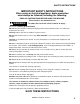
SAFETY INSTRUCTIONS IMPORTANT SAFETY INSTRUCTIONS When using an electrical appliance, basic precaution must always be followed, including the following: READ ALL INSTRUCTIONS BEFORE USING THIS MACHINE. This machine is for commercial use. ! WARNING: To reduce the risk of fire, electric shock, or injury: Connect to a properly grounded outlet. Do not leave the machine unattended. Unplug machine from outlet when not in use and before maintenance or service. Use only indoors.
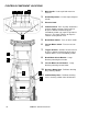
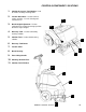
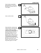
CONTROLS/COMPONENT LOCATIONS 8 9 5 4 6 1. Main Handle. Used to pull and maneuver machine. 2. Handle Adjustment. Used to adjust height of handle. 3. Electrical Cord. 4. Solution Switch. Turns on pump. Continuous position (bottom) activates electro-valve to dispense solution to floor through jets. Intermittent position (up) requires operator to depress 1 of 3 trigger switches to dispense solution. Center position is off. 5. Brush Motor Switch. Turns on brush motor. 6. Vacuum Motor Switch.
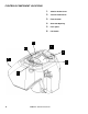
CONTROLS/COMPONENT LOCATIONS 1. Solution Accessory Tool Hookup. Used for various auxiliary cleaning tools. 2. Vacuum Hose Door. Used to connect various auxiliary 1 ½ inch cleaning tool vacuum hoses. 3. Brush Height Adjustment. Used to regulate brush height from storage position to various carpet heights. 4. Recovery Tank. Used to collect dirty cleaning solution. 5. Solution Tank. Used to hold cleaning solution. 6. Recovery Tank Dome. 7. Vacuum Shoe. 8. Brush Housing. 9.
CONTROLS/COMPONENT LOCATIONS 1. Solution Intake Cover. 2. Vacuum Intake Cover. 3. Float Shut-Off. 4. Clean-Out Opening. 5. Pour Spout. 6. Lift Handle.
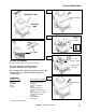
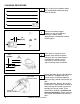
FILLING OPERATIONS STEP 1 RECOVERY TANK Remove recovery tank SOLUTION TANK STEP 2 or Add water 8 gal. (30.3 ltr.) 140°F (60°C) FILL LINE STEP 3 FILLING THE ADMIRAL 8 – 16oz. (237ml – 473ml) NOTE: Use clean bucket of water to fill solution tank Add cleaning chemical Do not put defoamer, solvents, spotter or prespray chemicals in the solution tank. Do not allow water to spill into vacuum motor inlet. Dry spillage from top of solution tank before replacing recovery tank.
OPERATIONS STEP 1 STEP 2 STEP 3 1/8in (3mm) CORRECT Remove electrical cord and literature from recovery tank. Fill solution tank (see filling instructions page 6). Plug cord into grounded outlet. Note: Be sure dome is seated on recovery tank, and float shut-off is installed correctly. Adjust brush to proper setting. Note: For good operation the brush must skim the carpet. If circuit breaker trips raise brush to prevent damage to motor or carpet.
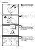
OPERATIONS Adjust handle to comfortable operating position. Tip machine back by main handle to move to starting point. STEP Lower machine to floor. STEP Select continuous setting to start solution spray or select intermittent setting to enable use of trigger switches to start solution spray. The intermittent setting requires the operator to hold any one of the three trigger switches in the “on” position with the fingers, and is typically used in small areas where short cleaning passes are made.
CLEANING PROCEDURE STEP 1 STEP 2 1ft. (30cm) OFF STEP 1in. (25mm) 3 SOLUTION INTAKE COVER VACUUM INTAKE COVER 9 STEP 4 Start at wall closest to power outlet. Pull straight back without pushing down on handle. Release intermittent trigger switches or turn off continuous setting on solution switch approximately 1 foot before ending cleaning pass. Push down on handle to raise vacuum shoe and brush before moving to the next cleaning pass.
CLEANING PROCEDURE Use right side of machine for cleaning against walls. STEP After cleaning, turn off all controls, return brush to storage position and carefully unplug machine. STEP 5 6 OFF OFF To speed drying, use a Windblower™ fan. STEP Empty recovery tank by releasing dump hose. Use a hose with cold water to clean out the recovery tank. Also drain solution tank after each use.
ACCESSORY TOOL USAGE STEP 1 Use only one of the following acceptable accessory tools. 86000020 – PRV NO. HT 86000000 – PRV NO. DDH 86041150 – PRV NO. DH 86031540 – PRV NO. 39504 86000610 – PRV NO. 89227 86000600 – PRV NO. 89226 Pull back collar and insert over machine mounted fitting, then release collar to lock into place. STEP 2 STEP 3 SOLUTION BRUSH INT VACUUM ON Lift door on front of vacuum shoe and insert 1 ½ inch hose cuff into hole.
TROUBLESHOOTING CHART PROBLEM CAUSE SOLUTION 1. Is the cord plugged in. 1. Plug in cord. 2. Circuit breaker tripped in building. 2. Reset breaker 3. Faulty switch. 3. Call for service. 4. Faulty power cord or pigtail. 4. Call for service. Vacuum Motor Will Not 1.Vacuum circuit breaker tripped. 1.Reset breaker Run 2.Faulty main vacuum switch. 2.Call for service. 3.Loose wiring. 3.Call for service. 4.Faulty vac motor. 4.Call for service. Vacuum Motor Runs But 1.Debris lodged in vac shoe.
THIS PAGE LEFT INTENTIONALLY BLANK 13 ADMIRAL 86038270 05/22/07
WIRING DIAGRAM 86268290 PRV NO. 88229 86268460 PRV NO. 88333 86268430 PRV NO. 88323 FILTER 86003650 PRV NO. 34362 86268370 PRV NO. 88276 86268430 PRV NO. 88323 86238830 PRV NO. 41355 86268900 PRV NO. 88655 86238840 PRV NO. 41356 86266720 PRV NO. 880043 86268430 - PRV NO. 88323 86268420 PRV NO. 88317 86268750 PRV NO. 88567 86238820 PRV NO. 41351 86001240 PRV NO.
MAINTENANCE PERIODIC MAINTENANCE Twice a month, flush a white vinegar solution (One quart vinegar to two gallons of water) or anti-browning solution (mixed as directed) through the extractor. This will prevent build-up of alkaline residue in the system. If spray jets become clogged, remove the spray tips, wash them thoroughly, and blow-dry. NOTE: Always store machine with brush in “Store” position. NOTE: Do not use pins, wire, etc. to clean nozzles as this could destroy spray pattern.
MAINTENANCE ! WARNING: ONLY QUALIFIED MAINTENANCE PERSONNEL ARE TO PERFORM THE FOLLOWING REPAIRS. VACUUM MOTOR REPLACEMENT 1. Turn off all switches and unplug machine. 2. Remove recovery tank. 3. Remove the (2) screws that fasten the solution tank to the frame, and tilt tank back to expose the inside of the frame. 4. Locate the vacuum motor wires and disconnect at the connector. Close the solution tank. 5. Remove the (6) screws holding the vacuum motor cover (p/n 86003080 – PRV NO.
MAINTENANCE SOLUTION PUMP REPLACEMENT 1. Turn off all switches and unplug the machine. 2. Remove recovery tank. 3. Remove the (2) screws that fasten the solution tank to the frame, and tilt tank back to expose the inside of the frame. 4. Remove solution hoses from fittings in pump. 5. Remove the (2) screws that fasten the pump to the frame. 6. Reverse process to install pump. Pump Replacement Parts for Shurflo 100 psi (86026400 – PRV NO. 65254) PumpHead 86251040 PRV NO.
TECHNICAL SPECIFICATIONS POWER TYPE GENERAL DIMENSIONS/WEIGHT ELECTRICAL: 230-240 V, 7 A, 50 HZ Vacuum shoe: 17” (43.18 cm) cast aluminum with spring loaded down pressure ELECTRIC VACUUM MOTOR: (1) –3 stage, 1 hp, 99 cfm (2.80 cubic meters/min.) Waterlift – 117” (297cm) WHEELS: (2) 10” dia. (25 cm) wheels by 2” WEIGHT: 92 lbs. (42 kg) BRUSH: (1) 15” (38.1 cm.) LENGTH: 35” (89 cm) SOLUTION PUMP: 100 PSI, diaphragm style, internal bypass HEIGHT: 42” (107 cm) SOLUTION CAPACITY: 8 gallons (30.
FRAME ASSEMBLY 30 7 19 18 15 (SEE PG. 31) A 21 B 12 33 11 28 10 3 34 31 6 C 5 (SEE PG.
FRAME ASSEMBLY REF PART NO. PRV NO.
BRUSH ASSEMBLY 31 15 25 11 7 25 29 30 8 16 12 26 24 38 18 16 30 39 10 22 34 4 44 45 36 47 40 37 33 41 26 32 17 28 35 3 43 21 13 42 1 27 6 19 14 17 23 20 30 25 29 25 46 3 9 2 5 21 ADMIRAL 86038270 05/22/07
BRUSH ASSEMBLY REF PART NO. PRV NO.
PUMP ASSEMBLY 3 20 29 29 17 4 13 28 10 16 8 2 16 21 23 18 1 12 19 15 20 11 26 9 7 25 22 22 25 D 6 (SEE SOLUTION TANK) 26 23 24 27 ADMIRAL 86038270 05/22/07 5
PUMP ASSEMBLY REF PART NO. PRV NO.
PUMP ASSEMBLY PRIOR TO S/N 1000153482 14 3 20 8 13 4 10 16 9 2 16 21 23 18 1 12 19 15 20 11 17 7 25 26 28 D (SEE SOLUTION (SEE PG.
PUMP ASSEMBLY PRIOR TO S/N 10000153482 REF PART NO. PRV NO.
VACUUM SHOE ASSEMBLY 1 4 11 7 13 10 2 12 3 5 8 6 7 11 27 ADMIRAL 86038270 05/22/07
VACUUM SHOE ASSEMBLY REF PART NO. PRV NO. QTY 1 2 3 4 5 6 7 8 9 10 11 12 13 86227350 86234760 86005810 86006790 86275120 86006840 86008130 86010620 86010630 86010700 86003780 86008120 05016 27674 57245 70351 70360 70390 73958 85039 OPEN 87013 87074 35171 73955 4 1 4 2 4 4 8 1 4 8 1 2 DESCRIPTION SERIAL NO. FROM NOTES: ARM, VAC SHOE PARALLEL COVER, ACCESSORY PORT NUT, 1/4-20 HEX NYLOCK SS SCR, 10-32 X 3/8 HHTR W/STAR SCR, 1/4-20 X.75 PPHMS PHIL SCR, 1/4-20 X 1 FHCS PLTD SPACER, 3/8ODX.058WX.
CONTROL PANEL ASSEMBLY 29 ADMIRAL 86038270 08/30/13
CONTROL PANEL ASSEMBLY SERIAL NO. FROM REF PART NO. PRV NO.
SOLUTION TANK ASSEMBLY 6 13 3 16 7 12 10 20 15 7* (SEE FRAME) 30 A 11 19 14* 18 24* 8 9 17* 2 32 26 1 25 18 22* 4 B 28 (SEE FRAME) 29 31 23* 21* 5* 31 16 27 ADMIRAL 86038270 05/22/07 D (SEE PUMP) 16 27
SOLUTION TANK ASSEMBLY REF PART NO. PRV NO.
RECOVERY TANK ASSEMBLY 16 15 5 E 18 7 11 4 12 8 10 E 1 14 9 12 13 17 2 6 11B 3 10B 1B 14B 12 33 ADMIRAL 86038270 05/22/07
RECOVERY TANK ASSEMBLY REF PART NO. PRV NO.
SUGGESTED SPARE PARTS 35 PART NO. PRV NO. 86001140 86001100 86000900 86004570 86241680 86004770 86010570 86003780 86230110 86002020 86007140 86007200 86005420 86007970 86230760 86135330 86003330 86003630 86006240 12514 11045 09019 44067 44073 47477 84165 35171 14312 14949 72130 72162 53791 73864 140216 140688 28061 34351 66227 DESCRIPTION BRUSH, 15L X 3.38OD BELT, 180J6 MICRO-V BEARING, 1.125ODX.500IDX.
ADMIRAL 86038270 05/22/07 36