Cadet 7 - 115V Carpet Extractor Operating Instructions (ENG) MODELS: CDT7 10080220 From Serial Number (Ref No1*) *See Serial Number Page or call manufacturer 86401410-A 02/26/15
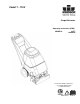
Machine Data Label This carpet extractor is an electrical powered, portable carpet extractor intended for commercial use. The appliance sprays a cleaning solution onto the carpet agitates the wet carpet, and then extracts the soiled solution back into the unit's recovery tank. The appliance is fitted with and a hand tool for cleaning upholstery and stairs. Warranty Registration Thank you for purchasing a Kärcher North America product. Warranty registration is quick and easy.
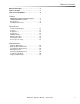
Table of Contents Machine Data Label . . . . . . . . . . . . . . . . . . . . . . . . . . 2 Table of Contents . . . . . . . . . . . . . . . . . . . . . . . . . . . 3 How To Use This Manual . . . . . . . . . . . . . . . . . . . . . 4 Safety IMPORTANT SAFETY INSTRUCTIONS . . . . . . . . . 5 HAZARD INTENSITY LEVEL . . . . . . . . . . . . . . . . . . 7 Safety Labels . . . . . . . . . . . . . . . . . . . . . . . . . . . . . . 9 Grounding Instructions:. . . . . . . . . . . . . . . . . . . . . .
How To Use This Manual This manual contains the following sections: • • • • • How to Use This Manual Safety Operations Maintenance Suggested Spare Parts The SAFETY section contains important information regarding hazardous or unsafe practices of the machine. Levels of hazards are identified that could result in product damage, personal injury, or severe injury resulting in death. The OPERATIONS section is to familiarize the operator with the operation and function of the machine.
Safety IMPORTANT SAFETY INSTRUCTIONS When using this machine, basic precaution must always be followed, including the following: READ ALL INSTRUCTIONS BEFORE USING THIS MACHINE. To reduce the risk of fire, electric shock, or injury: Connect to a properly grounded outlet. See Grounding Instructions. Do not leave the machine unattended. Unplug machine from outlet when not in use and before maintenance or service. Use only indoors. Do not use outdoors or expose to rain.
Safety IMPORTANTES MESURES DE SÉCURITÉ L’utilisation d’un appareil électrique demande certaines précautions: LIRE TOUTES LES INSTRUCTIONS AVANT DE FAIRE FONCTIONNER (CET APPAREIL). ! AVERTISSEMENT Pour réduire les risques d’incendie, de choc électrique ou de blessure: Cet appareil ne doit être connecter qu a des prises ayant une sortie de terre. Ne pas laisser l’appareil sans surveillance lorsqu’il est branché. Débrancher lorsque l’appareil n’est pas utilisé et avant l’entretien.
Safety The following symbols are used throughout this guide as indicated in their descriptions: HAZARD INTENSITY LEVEL There are three levels of hazard intensity identified by signal words -WARNING and CAUTION and FOR SAFETY. The level of hazard intensity is determined by the following definitions: WARNING - Hazards or unsafe practices which COULD result in severe personal injury or death. CAUTION - Hazards or unsafe practices which could result in minor personal injury or product or property damage.
Safety Les symboles ci-dessous sont utilisés à travers ce manuel comme illustré dans leurs descriptions : DEGRÉS DE RISQUES EN CAS DE DANGER Il existe trois degrés de risques identifiés par les termes signalétiques –AVERTISSEMENT et ATTENTION et POUR VOTRE SÉCURITÉ. Le degré de risque est défini de la manière suivante : AVERTISSEMENT - Dangers ou méthodes dangereuses qui POURRAIENT provoquer de graves blessures ou entraîner la mort.
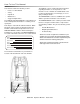
Safety Safety Labels NOTE: These drawings indicate the location of safety labels on the machine. If at any time the labels become illegible, promptly replace them. EMPLACEMENT DE L'ÉTIQUETTE DE SÉCURITÉ REMARQUE : Ces dessins indiquent l'emplacement des étiquettes de sécurité sur la machine. Si, à tout moment, les étiquettes deviennent illisibles, contactez votre représentant autorisé pour un remplacement rapide.
Safety Electrical: In the USA, this machine operates on a standard 15 amp 115V, 60 Hz, A.C. power circuit. The amp, hertz, and voltage are listed on the data label found on each machine. Using voltages above or below those indicated on the data label will cause serious damage to the motors.
Notes 86401410 Operators Manual - Cadet 115V 11
Operations Technical Specifications ITEM Weight DIMENSION/CAPACITY 92lbs (42kg) Length 41 inches (104cm) Height 34 inches (86.4cm) Width 17.5 inches (44.5cm) Wheels 2x 10 in (25 cm) Diameter wheels by 2 in Solution Spray 2 Quick Change Jets Power Cable 50 Feet (12.7 m) Vacuum Shoe 17 in (43.2 cm) cast aluminum with spring loaded down pressure. Electrical 115 V, 15 A, 60 HZ Electrical Vacuum Motor 3 stage, 1.5 hp, 100 cfm (2.80 cubic meters/min.
Operations HEIGHT LENGTH WIDTH This appliance is not intended for use by persons (including children) with reduced physical, sensory or mental capabilities, or lack of experience and knowledge, unless they have been given supervision or instruction concerning use of the appliance by a person responsible for their safety. Children should be supervised to ensure that they do not play with the appliance.
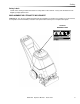
Operations Controls 1. Main Handle. Used to pull and maneuver machine 2. Electrical Cord. 3. Pump Switch. Turns on pump and enables spray. 4. Brush/Spray switch. Turns on brush motor and activates electro-valve to dispense solution to floor through jets. Intermittent, off, and continuous settings. 5. Vacuum Motor Switch. Turns on vacuum motor 6. Brush Motor Circuit Breaker. 6 amp. Breaker protecting brush motor. 1 4 7 7. Vacuum Motor Circuit Breaker. 15 amp. Breaker protecting vacuum motor. 8.
Operations Components 1. Solution Accessory Tool Hookup. Used for various auxiliary cleaning tools. 2. Vacuum Hose Door. Used to connect various auxiliary 1 1/2 inch cleaning tool vacuum hoses. 3. Brush Height Adjustment. Used to regulate brush height from storage position to various carpet heights. 4. Recovery Tank. Used to collect dirty cleaning solution. 5. Solution Tank. Used to hold cleaning solution. 6. Recovery Tank Dome. 7. Vacuum Shoe. 8. Brush Housing. 9. Front Lifting Handle. 10.
Operations Components 1. Solution Intake Cover. 2. Vacuum Intake Cover. 3. Float Shut-Off. 4. Clean-Out Opening. 5. Pour Spout. 6. Lift Handle.
Operations Filling the Cadet NOTE: Use clean bucket of water to fill solution tank. Do not put defoamer, solvents, spotter or prespray chemicals in the solution tank. Do not allow water to spill into vacuum motor inlet. Dry spillage from top of solution tank before replacing recovery tank.
Operations Filling the Cadet - continued 1. Remove literature from recovery tank. 2. Remove the recovery tank from the machine. 3. Fill the Solution Tank with 7 gallons (26.5 ltr.) of water, that is no more than 140°F/60°C. 4. Add 7oz-14 oz. (207ml-414ml) of cleaning chemical.
Operations 5. Replace the Recovery Tank on the machine. Machine Operation 1. Plug cord into grounded outlet. NOTE: Be sure dome is seated on recovery tank, and float shut-off is installed correctly. 2. Adjust brush to proper setting. NOTE: For good operation the brush must skim the carpet. If circuit breaker trips, raise brush to prevent damage to motor or carpet. 3. Turn on pump and vacuum motor switches ("ON"="I").
Operations 4. Tip machine back by main handle to move to starting point. 5. Lower machine to floor. 6. Select intermittent or continuous switch setting to turn on brush and start solution spray. The intermittent setting requires the operator to hold the switch in the "on" position with the thumb, and is typically used in small areas where short cleaning passes are made.
Operations 2. Release intermittent trigger switch or turn off continuous setting on solution switch approximately 1 foot before ending cleaning pass. 3. Push down on handle to raise vacuum shoe and brush before moving to the next cleaning pass. Overlap brush contact area a minimum of 1inch. 4. During operation, observe the following: The Cadet is equipped with clear internal covers to facilitate operator viewing of dirty solution and vacuum air flow. During operation, observe the vacuum intake cover.
Operations 6. After cleaning, turn off all controls, return brush to storage position and carefully unplug machine. 7. To speed drying, use an air moving fan. 8. Empty recovery tank by releasing dump hose. Use a hose with cold water to clean out the recovery tank. Drain solution tank after each use.
Operations Accessory Tool Usage Use only one of the following acceptable accessory tools. 8.600-061.0 - STANDARD WAND 8.600-006.0 - VSM DUSTING TOOL W/MTG CLIP 8.603-154.0 - HOSE ASM, CST HANDTOOL U19821 1. Pull back collar and insert over machine mounted fitting, then release collar to lock into place. 2. Lift door on front of vacuum shoe and insert 1 ½ inch hose cuff into hole. 3. Turn on vacuum motor switch and set solution switch to intermittent position.
Maintenance Maintenance Check machine for cord damage. Check recovery dome and gasket for damage and cleanliness. Check brush - should be clean with no lint or strings attached. Inspect vacuum shoe for blockage; remove fibers with coat hanger, etc. Check hoses for wear, blockages, or damage. Check handles, switches, and knobs for damage. Check vacuum motor intake filter and clean. Run one gallon of water through system. Clean out recovery tank and check float valve to make sure it moves freely.
Maintenance Periodic Maintenance Twice a month, flush a white vinegar solution (One quart vinegar to two gallons of water) or anti-browning solution (mixed as directed) through the extractor. This will prevent build-up of alkaline residue in the system. If spray jets become clogged, remove the spray tips, wash them thoroughly, and blow-dry. 9. Check float and shut-off screen and clean as necessary. NOTE: Always store machine with brush in "Store" position. NOTE: Do not use pins, wire, etc.
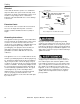
Maintenance Vacuum Motor Replacement Only qualified maintenance personnel are to perform the following repairs. Seul le personnel d'entretien qualifié peut effectuer des réparations 1. Turn off all switches and unplug machine. 2. Remove recovery tank. 3. Remove the (2) screws that fasten the solution tank to the frame, and tilt tank back to expose the inside of the frame. 4. Locate the vacuum motor wires and disconnect at the connector. Close the solution tank. 5.
Maintenance Belt Replacement Only qualified maintenance personnel are to perform the following repairs. Seul le personnel d'entretien qualifié peut effectuer des réparations 1. Turn off all switches and unplug machine. 2. Remove recovery tank and brush. 3. Remove the (2) screws that fasten the solution tank to the frame, and tilt tank back to expose the inside of the frame. 4. Loosen the (4) screws that hold the brush motor in place and slide motor forward to release tension in belt. 5.
Maintenance Solution Pump Replacement Only qualified maintenance personnel are to perform the following repairs. Seul le personnel d'entretien qualifié peut effectuer des réparations 1. Turn off all switches and unplug the machine. 2. Remove recovery tank. 3. Remove the (2) screws that fasten the solution tank to the frame, and tilt tank back to expose the inside of the frame. 4. Remove solution hoses from fittings in pump. 5. Remove the (2) screws that fasten the pump to the frame. 6.
Maintenance Troubleshooting Chart PROBLEM No Power, Nothing Runs Vacuum Motor Will Not Run CAUSE Is the cord plugged in. Circuit breaker tripped in building. Faulty switch. Faulty power cord or pigtail. Plug in cord. Reset breaker. Call for service. Call for service. Vacuum circuit breaker tripped. Reset breaker. Faulty main vacuum switch. Loose wiring. Faulty vac motor. Call for service. Call for service. Call for service. See "Brush Replacement" in maintenance section. Remove debris from vac shoe.
Suggested Spare Parts PART NO. 86001140 86001100 86004570 86004580 86003630 86003330 86007970 86135320 30 DESCRIPTION BRUSH, ASM, 15 IN BELT, 180J6 MICRO-V JET BODY, MINI PROMAX BODY JET, MINI PROMAX 9504 FLOAT, SHUT-OFF DOME ASM, CLP FAM STRAINER, 3/8 IN.
Notes 86401410 Operators Manual - Cadet 115V 31