Operator’s Manual Series 300 Automatic Transfer Switches H–design 600 through 1200 amps DANGER is used in this manual to warn of high voltages capable of causing shock, burns, or death. TABLE OF CONTENTS section INSTALLATION . . . . . . . . . . . . . . . . . . . . . . . . . . 1 ! WARNING is used in this manual to warn of possible personal injury. SEQUENCE OF OPERATION . . . . . . . . . . . . . 2 TESTING & SERVICE . . . . . . . . . . . . . . . . . . . .
Nameplate Catalog Number Identification The Transfer Switch nameplate includes data for each specific ASCO Series 300 ATS. Use the ATS only within the limits shown on this nameplate. A typical Catalog Number is shown below with its elements explained.
ASCO Series 300 Automatic Transfer Switches (ATSs) are Listed under Underwriters Laboratories UL 1008 Standard for Safety for Automatic Transfer Switches. All control features are UL Component Recognized, which assures that ASCO automatic transfer switches meet OSHA Safety Requirements and will be acceptable to electrical inspectors. ASCO Series 300 Automatic Transfer Switches are suitable for emergency and standby system applications.
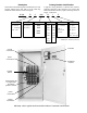
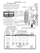
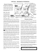
Controller membrane controls neutral connections power connections Transfer Switch terminal block TB for engine start and switch position contacts power connections neutral connections 1200 amp.
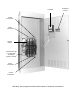
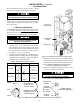
SECTION 1 Series 300 Automatic Transfer Switches are factory wired and tested. Installation requires skid removal then securing the enclosure to the supporting foundation. Remove the Shipping Skid Open the front door and remove the four lag screws (2 in front, 2 in rear) securing enclosure to the wood skid. Supporting Foundation The supporting foundation for the enclosure must be level and straight.
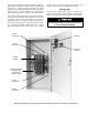
INSTALLATION (continued) Engine Starting Contacts Customer connections for engine control contact and TS auxiliary contacts connections are located on terminal block TB which is mounted on the front lower left of the transfer switch. Refer to wiring diagram provided with the Series 300 ATS and connect the engine start wires to the appropriate terminals. See Figure 1–1 and Table A. Table A. Engine start connections.
INSTALLATION (continued) Functional Test The Functional Test consists of three checks: manual operation, voltage checks, and electrical operation. ! Do these checks in the order presented to avoid damaging the automatic transfer switch. Read all instructions on the Wiring Diagram and labels affixed to the automatic transfer switch. Note the control features that are provided and review their operation before proceeding.
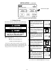
INSTALLATION (continued) observe these lights Figure 1–5. St andard controls and indicators. 2 – Voltage Checks First check nameplate on transfer switch; rated voltage must be the same as normal and emergency line voltages. ! Verify that the feeders have been connected to the proper lugs. Close the normal source circuit breaker. The Normal Transfer 1 Switch Position and the Normal Source Accepted lights should come on.
INSTALLATION (continued) observe these lights press this button Figure 1–6. Standard controls and indicators. 3 – Electrical Operation First check nameplate on transfer switch; rated voltage must be the same as normal and emergency line voltages. ! The normal source must be available and the generator 1 must be ready to start. Check that the Normal Source Accepted light is on. Press and hold the Transfer Test button until the engine starts 2 and runs. This should happen within 15 sec.
SECTION 2 SEQUENCE OF OPERATION Lights show position of transfer switch. Transfer To Emergency The sequence for load transfer to emergency source begins automatically when normal source voltage falls below the preset dropout point or when Transfer Test button is pressed. An under voltage condition on any phase of the normal source is detected by the sensor. Lights show the sources accepted. Light for built–in engine exercise timer: ➤ blinks rapidly when button is held 5 sec.
SECTION 3 TESTING & SERVICE PREVENTIVE MAINTENANCE DISCONNECTING THE CONTROLLER Reasonable care in preventive maintenance will insure high reliability and long life for the automatic transfer switch. The harness disconnect plugs are furnished for repair purposes only and should not have to be unplugged. If the controller must be isolated, follow these steps carefully. Operate the switch at least once a month. Perform this four step Electrical Operation Test. This is a test with load transfer.
TESTING & SERVICE (continued) MANUAL LOAD TRANSFER 1. Open normal and emergency source circuit breakers. This procedure will manually transfer the load if the controller is disconnected. 2. Use the maintenance handle to manually operate transfer switch to the opposite source. See page 1–3, Manual Operation Test. ! Do not manually operate the transfer switch until both power sources are disconnected: open both circuit breakers. 3.
SECTION 4 ADJUSTMENTS Time Delay Adjustment To change a setting, follow procedure on page 4-2. Use Table 4-1 as a guide to time delay values and their corresponding adjustment DIP switch or potentiometer. Standard time delays are set to customer specifications (if none specified, standard factory settings are used). Table 4-1.
ADJUSTMENTS ! (continued) cover Do not make any setting changes while the controller is energized. thumb latch How to Change a Setting 1. Prevent the transfer switch from operating by disconnecting one source first, then the other, as follows: a. b. hook on left side If the transfer switch is in the Normal position, open the emergency source circuit breaker. Turn the engine starting control to off. Then open the normal source circuit breaker. Figure 4-1. Controller cover latch.
SECTION 5 CONTROL FEATURES – ENGINE EXERCISERS These timers periodically exercise the emergency engine-generator plant. They can be set to exercise with or without load transfer, or they can be completely disabled. The engine-generator should be exercised under load once a week for a minimum time period of 20 minutes, or follow the recommendations of the engine-generator set manufacturer. Refer to page 4–2 for location of DIP switches, battery (provided), and jumper block in the controller.
CONTROL FEATURES (continued) Optional Accessory 11BG – SOURCE AVAILABILITY SIGNAL & PROGRAMMABLE ENGINE EXERCISER MODULE 2–line display connections for source availability signal contacts 3 buttons Figure 5–2. Accessory 11BG module (mounted behind operator interface and connected to the controller) includes source availability signal contacts and a programmable engine exerciser.
CONTROL FEATURES (continued) How to Set Optional Programmable Engine Exerciser (part of Acc. 11BG module) For example, if the user wants the exerciser to run every other Saturday at 3 PM, the proper configuration would be: “Alt Sat @ 15:00” NOTE: When choosing bi–weekly operation, the exerciser will always run on the week designated “(1)” on the date display. Hazardous voltage capable of causing shock, burns, or death is used in this transfer switch.
CONTROL FEATURES (continued) INPHASE MONITOR FOR MOTOR LOAD TRANSFER LOAD DISCONNECT FEATURE Inphase monitoring logic controls transfer and retransfer of motor loads, so that inrush currents do not exceed normal starting currents. It avoids nuisance tripping of circuit breakers and mechanical damage to motor couplings. The Motor Load Transfer feature is built into the controller. DIP switch S1 (actuator 5) activates this feature: right = ON, left = OFF.
CONTROL FEATURES (continued) OPTIONAL STRIP HEATER (Accessory 44) Accessory 44 Strip Heater is designed to keep ambient temperatures within the Automatic Transfer Switch enclosure at acceptable levels. This accessory consists of a mounting bracket with strip heater, thermostat, and terminal block. A transformer with fuses is included when the power for the assembly is derived from voltages above 120 V ac. The 120 V ac customer powered assembly does not include a transformer.
A accessories, 5–2, 5–5 auxiliary circuits, 1–2 B battery, 4–2, 5–1 G INDEX help, service 3–2 cleaning, 3–1 connections engine control contact, 1–2 line, 1–1 contact position indicators, 1–3 contacts auxiliary, 1–2 engine control, 1–2 main, 1–3, 3–1 source availability signal, 5–2 control features, 5–1 load disconnect, 5–4 motor load transfer, 5–4 plant exerciser, 5–1, 5–2, 5–3 controller, 4–1, 4–2 codes, cover cover removal, 4–2 disconnecting, 3–1 time delay potentiometers, 4–2 D DIP Switches, 4–1, 4