Installation Manual 5100 Series, Catalog 5150 Connectivity Module For use with Automatic Transfer Switches & Power Manager Section 1 Page Welcome............................................................................................................. ii Overview, Specifications, How to View Pages after Installation ....................... iii Installation on Automatic Transfer Switches (7000, 4000, 300, 940/962) ......................... 1-1 on stand-alone Power Manager, Test Communications .......
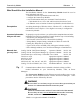
Connectivity Module Welcome ii Who Should Use this Installation Manual This Installation Manual for the Connectivity Module should be used to assist individuals who will: • install the Connectivity Module (mount and wire) • configure the Connectivity Module • enter in information about your Automatic Transfer Switches (7000 & 4000 Series, Series 300, ASCO 940,962,436,434,447,448) • use Ethernet access to monitor Connectivity Module (connected devices) Prerequisites A working knowledge of Windows 2000 ®,
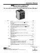
iii Overview, Specifications, How to View Pages Overview The Connectivity Module brings together several different serial devices that communicate at different baud rates and with different protocols to a common Ethernet media. It can communicate with up to eight clients, such as Web applications (web pages), Vpi, or third-party Modbus ® devices simultaneously over Ethernet media. Specifications Power Requirements: 24 V dc nominal (8 – 28 V dc) 1.5 Watt, UL Class 2 power supply, if needed.
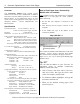
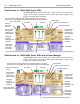
Connectivity Module Installation 1-1 How to Install the Connectivity Module on 7000 & 4000 Series and Series 300 ATSs How to Install the Connectivity Module on ASCO 940/962 ATSs The Connectivity Module mounts on a DIN rail under the ATS Controller (Group 5 & 1). A short serial cable connects the Connectivity Module to the Controller. If a Power Manager is present, a long serial cable connects the Connectivity Module to the Power Manager.
1-2 Installation Connectivity Module How to Install the Connectivity Module for a stand-alone Power Manager How to Test Communication to the Connectivity Module The Connectivity Module mounts on a DIN rail near the Power Manager. A long serial cable connects the Connectivity Module to the Power Manager. Refer to installation drawings provided and follow the steps below to install the Connectivity Module.
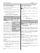
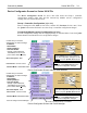
Connectivity Module Installation 1-3 How to View & Change Configuration Pages from a Connectivity Module How to View Pages from a Connectivity Module after it is installed To view and change configuration pages on a client computer, follow these steps: After installation, testing, and configuration is completed, to view pages on a client computer, follow these steps: 1. Be sure that your computer is connected to the Internet. 2. Start Microsoft Internet Explorer browser on computer. 3.
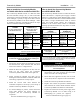
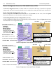
2-1 7000 Series ATSs Connectivity Module Device Configurator Screen for 7000 & 4000 Series ATSs The Device Configurator Screen for 7000 & 4000 Series ATSs shows the Group 5 controller configuration settings (right side) and Connectivity Module (server) configuration settings (left side) for the selected ATS. Group 5 Controller Configuration (right side) Enter or change the ATS Name (8 char. max.)and the ATS Location (20 char. max.).
Connectivity Module 7000 Series ATSs 2-2 Device Configurator Screen for 7000 & 4000 Series ATSs with a Power Manager If a Power Manager is used with a 7000 & 4000 Series ATS, a button appears on the lower left corner of the Connectivity Module Device Configurator screen. Press the Config PM button to display the Power Manager Configuration screen (right side). Power Manager Configuration Enter or change the Power Manager Name (8 char. max.) and Location (20 char. max.).
2-3 7000 Series ATSs Connectivity Module Detail Screen for 7000 & 4000 Series ATSs The Detail Screen for 7000 & 4000 Series ATSs shows the switch location, ratings, timer settings, actual timer values, pickup and dropout settings, event logging, and other status indications.
Connectivity Module Series 300 ATSs 3-1 Device Configurator Screen for Series 300 ATSs The Device Configurator Screen for Series 300 ATSs shows the Group 1 controller configuration settings (right side) and the Connectivity Module (server) configuration settings (left side) for the selected ATS. Group 1 Controller Configuration (right side) Enter or change the ATS Name (8 char. max.) and the ATS Location (20 char. max.).
3-2 Series 300 ATSs Connectivity Module Device Configurator Screen for Series 300 ATSs with a Power Manager If a Power Manager is used with a Series 300 ATS, a button appears on the lower left corner of the Connectivity Module Device Configurator screen. Press the Config PM button to display the Power Manager Configuration screen (right side). Power Manager Configuration Enter or change the Power Manager Name (8 char. max.) and Location (20 char. max.
Connectivity Module Series 300 ATSs 3-3 Detail Screen for Series 300 ATSs The Detail Screen for Series 300 ATSs shows the switch location, ratings, timer settings, actual timer values, pickup and dropout settings, and other status indications.
4-1 ASCO 940/962 ATSs Connectivity Module Device Configurator Screen for ASCO 940/962 ATSs The Device Configurator Screen for ASCO 940/962 ATSs shows the Group 7A controller configuration settings (right side) and the Connectivity Module (server) configuration settings (left) for the selected ATS. Group 7A Controller Configuration (right side) Enter or change the ATS Name (18 char. max.) and ATS Nominal Voltage (must be entered to get correct reading).
Connectivity Module ASCO 940/962 ATSs 4-2 Detail Screen for ASCO 940/962 ATSs The Detail Screen for ASCO 940/962 ATSs shows the switch location, ratings, timer settings, actual timer values, pickup and dropout settings, and other status indications. ATS one-line icon shows position & source status (green or red circle means source is acceptable, grey circle means source is not acceptable) Status of Emergency S ATS name Status of Normal Source Actual voltage reading from ATS controller.
5-1 Stand-Alone Power Managers Connectivity Module Device Configurator Screen for Power Manager If a stand-alone Power Manager is used, a button appears on the lower left corner of the Connectivity Module Device Configurator screen. Press the Config PM button to display the Power Manager Configuration screen (right side). Power Manager Configuration Enter or change the Power Manager Name and Location. Several configuration settings must be set appropriately as described below.
Connectivity Module Stand-Alone Power Managers 5-2 Detail Screen for Power Managers connected to a Load The Detail Screen for Power Managers shows energy levels, power measurements, settings, discrete I/O status, and other status information. PM name Settings Energy levels PM location Click to view Normal or Emergency energy data. Power measurements Actual voltage, current, and power readings from the PM.
5-3 Stand-Alone Power Managers Connectivity Module Detail Screen for Power Managers connected to a Generator Gen-set icon appears if Power Manager address is set to 33-43. The Detail Screen for Power Managers shows energy levels, power measurements, settings, discrete I/O status, and other status information. Settings PM name PM location Energy levels Power measurements Actual voltage, current, and power readings from the PM.
IP Address Subnet mask Gateway ATS Serial No. ATS Catalog No. Address set in ATS Controller* Address set in PM** Instructions: Fill in the information for each Connectivity Module (CM) with an Automatic Transfer Switch (ATS) and/or Power Manager (PM).
IP Address Subnet mask Gateway ATS Serial No. ATS Catalog No. Address set in ATS Controller* Address set in PM** Instructions: Fill in the information for each Connectivity Module (CM) with an Automatic Transfer Switch (ATS) and/or Power Manager (PM).
Group 5 Controller with or w/o Power Manager Xp 19200 bps TTL Protocol: Addressing: Connectivity Module side view and internal mode jumper settings R Protocol: Addressing: 1 - 31 Group 7/7A Controller 9600 bps RS-485 with or w/o PM Xp 9600 bps TTL J1 J2 TTL CONNECTIVITY MODULE CAT.NO.
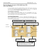
7000 Series Transfer Switch Group 5 Controller Group 5 Controller Address 1-32 19200 Baud Address 1-32 Address 1-32 19200 Baud 19200 Baud Cable Assy ASCO P/N 629798-001 Cable Assy ASCO P/N 629798-002 R Ethernet cable 10 Base T Max. 300 ft. Max. J1 CONNECTIVITY MODULE CAT.NO.5150 TX Link CH1 CH2 DIAG Reset R Ethernet cable 10 Base T Max. 300 ft. Max.
Connectivity Module Ethernet TCP/IP Network Connections in Windows 2000 A-1 How to Create an Ethernet TCP/IP Network Connection in Windows 2000 1. Start Windows, then click the Start button. Select Settings and Control Panel. 4. Click the Configure button to verify installation of the Ethernet card. 2. Click the Network and Dial-up Connections icon. 5. If the device status indicates “This device is working properly” then proceed to the next step and close this window. 3.
A-2 Ethernet TCP/IP Network Connections in Windows 2000 6. Install Internet Protocol by clicking the Install button. If the Internet Protocol (TCP/IP) is already installed, select it, click the Properties button, and proceed to step 9. Connectivity Module 9. If the computer is on the company network contact the facilities IT personnel for appropriate settings. If it is a stand-alone computer, enter the IP # for this computer that is listed on the Interface Diagram.
Connectivity Module Ethernet TCP/IP Network Connections in Windows NT A-3 How to Create an Ethernet TCP/IP Network Connection in Windows NT 1. Start Windows, then click the Start button. Select Settings and Control Panel. 2. Double-click the Network icon. 3. Click the Adapters tab. 4. Click the Properties button to verify installation of the Ethernet card. 5. If the device status indicates “This device is working properly” then proceed to the next step and close this window.
A-4 Ethernet TCP/IP Network Connections in Windows NT 6. Install Internet Protocol by clicking the Protocols tab. If the Internet Protocol (TCP/IP) is already installed, select it, click the Properties button, and proceed to step 9. 9. If the computer is on the company network contact the facilities IT personnel for appropriate settings. If it is a stand-alone computer, enter the IP # for this computer that is listed on the Interface Diagram. For example: IP address: Subnet Mask: Gateway: 7.
Connectivity Module Ethernet TCP/IP Network Connections in Windows XP A-5 How to Create an Ethernet TCP/IP Network Connection in Windows XP 1. Start Windows, then click the Start button. Select Settings and Control Panel. 4. Right click the Local Area Connection icon. 2. Click the Network and Internet Connections icon. 5. Click the Configure… button installation of the Ethernet card. 3. Click the Network Connections icon.
A-6 Ethernet TCP/IP Network Connections in Windows XP 6. If the device status indicates “This device is working properly” then proceed to the next step and close this window. Connectivity Module 8. If the computer is on the company network contact the facilities IT personnel for appropriate settings. If it is a stand-alone computer, enter the IP # for this computer that is listed on the Interface Diagram. For example: IP address: Subnet Mask: Gateway: 169.254.1.
Connectivity Module Troubleshooting A-7 Troubleshooting the Connectivity Module Listed below are possible problems, their causes, and possible solutions. DANGER To avoid possible shock, burns, or death, deenergize all electrical sources to the Automatic Transfer Switch, Power Manager, and Connectivity Module before working on it. DIAG light Problem Cause Solution DIAG red light blinks rapidly then stays on when the Connectivity Module is first powered up. Duplicate IP address.
A-8 Create Favorites folder, 3rd Party Modbus Configuration How to create a Favorites folder for ASCO device pages and copy it to another computer To create a favorites folder and copy it to another user’s computer, the administrator should follow these steps: 1. Open the first page and then pull down the Favorites manual and select Add to Favorites … This window will appear: 2. Click the New Folder button, type the new folder name as asco, then click the OK button. 3. Click folder asco and click OK. 4.
INDEX A K ATS information needed, ii, communication address form C Cable, communication, iii Change Password, 1-3 Communication error message, A-7 Configuration 7000 Series ATSs, 2-1, 2-2 4000 Series ATSs, 2-1, 2-2 Series 300 ATSs, 3-1, 3-2 ASCO 940/962 ATSs, 4-1 Power Managers, 5-1 Configuration parameters, iii Copy Favorites folder, A-8 Create Favorites folder, 1-3, A-8 D Detail Screens (View Pages) 7000 Series ATSs, 2-3 4000 Series ATSs, 2-3 Series 300 ATSs, 3-3 ASCO 940/962 ATSs, 4-2 Power Managers,