
Manual

5
FUNCTIONAL TEST (after installation)
After installing the Series 165 automatic transfer switch
perform the following three–part functional test.
1–MANUALOPERATION
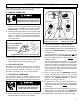
ELECTROCUTION – FLASH HAZARD
Do not manually operate the transfer
switch until utility and generator are
disconnected; open circuit breakers.
1. Put both the preferred source circuit breaker and the
alternate source circuit breaker feeding the automatic
transfer switch in the OFF position. Verify that ALL
POWER IS OFF ! (Seepage2forhandlelocation.)
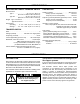
2. Grasp t he maintenance handle and turn it quickly with
your thumb and fingers to manually operate the transfer
switch. The sw itch should operate smoothly without
binding. If it does not, check for shipping damage or
construction debris.
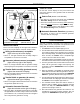
maintenance handle
With ALL POWER OFF
grasp maintenance
handle and turn it
quickly with your
thumb and fingers.
weight marked P (preferred) and A (alternate)
3. After checking the manual operation operate the handle
again quickly to return the transfer switch to the preferred
positi o n (letter P on the ro und weight facing you) .
2–VOLTAGECHECKS
The Series 165 automatic transfer switch is rated for
nominal 240 V ac at 60 Hz (as stated on the nameplate).
Verify that both your preferred and alternate sources are
also 240 V a c nominal, 60 Hz. See the wiring diagram.
3 – ELECTRICAL OPERATION
This procedure checks the electrical operation of the
automatic transfer switch. If the actual operation does not
follow this procedure, consult the T roubleshooting section.
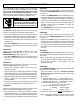
PERSONAL INJURY HAZARD
Install front cover before operation.
An el ectrical system fault could
cause a flash and cause injury.
!
1. Install the encl osure co ver and tighten the screws.
2. V erify that the generator battery is connected and that the
generator’s starting control s are set for automatic.
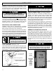
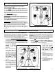
source acceptable lights
transf er switch on generator
(alternate source) light
test button
transfer switch on utility
(preferred source) light
3. Turn on the preferred source (utility) circuit breaker.
4. Turn on the alternate source (generator) circuit breaker.
5. Veri fy that UTILITY (preferred source) acceptable light is on.
6. V eri fy that the TRANSFER SWITCH on utility (preferred
source) l ight i s on.
7. This step will start the generator. Press and hold
the
Push to Test button until the GENERATOR (alternate
source) acceptable light comes on and stays on.Then
release the button.
This light indicates that the generator is running and
that its output voltage and frequency are acceptable.
Under typical conditions, the light should come on after
about 5 to 10 seconds. If the generator is running and
fails to produce the proper voltage and frequency after
60 seconds then a malfunction has occurred (consult
the Troubleshooting section).
8. About 15 seconds after the GENERATOR (alternate
source) acceptable light comes on, the automatic
transfer switch transfers the load from the utility to the
generator. The TRANSFER SWITCH on generator
(alternate source) light comes on.
9. The transfer switch stays connected to the generator for
5 minutes. Then the load is transferred back to the utility.
To bypass time delay, press and release
the Push to Te st
button again.
10. After lo ad retransfer to utili ty, the generator runs 1 minute
(without lo ad), then shuts down. The GENERATOR
acceptabl e li ght goe s off indicating that generator is off .
This compl etes the Functional T est. Proceed to next page.