
User guide
© Cummins 2008 3 TD_AS480 AVR_04.08_02_GB
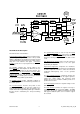
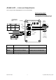
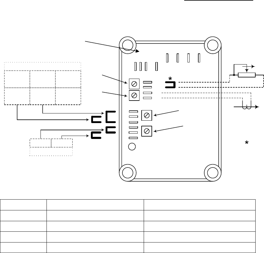
AS480 AVR – Links and Adjustments
refer to the generator wiring diagram for all connection details
Operation at 110Vac (optional)
- remove link(*) before fitting
- connect the 15k/1W sensing link
- the hand trimmer cannot be used in this mode
- Overload performance is limited in this mode.
F2
F1
7
8
DR
EB
F2
F1
2
1
S2
S1
D
C
B
50
HZ
60
LED
STABILITY
UFRO
VOLTS
DROOP
50Hz 60Hz
UFRO Linking
Link BDLink BC
Stability Linking
No Link
> 100kW
< 100kW
Slow
< 100kW
Fast
1k / 1W
Hand
Trimmer
(optional)
Droop
C/T
(optional)
Remove link
before fitting
Raise
Control Function Direction
VOLTS Generator output voltage setting Clockwise raises voltage
STABILITY Output voltage stability Clockwise increases stabilisation effect
DROOP Voltage droop for paralleling Clockwise increases drooping effect
UFRO Under-frequency 'Knee' point Clockwise decreases 'Knee' point
Refer to the Generator Wiring Diagrams for all Connection detail
connections for
excitation boost
unit