
Instruction Manual

FITTING AND OPERATING
©2006 3 TD_AS440 AVR_03.09_04_GB
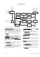
SUMMARY OF AVR CONTROLS
CONTROL FUNCTION DIRECTION
VOLTS TO ADJUST GENERATOR OUTPUT VOLTAGE CLOCKWISE INCREASES OUTPUT VOLTAGE
STABILITY TO PREVENT VOLTAGE HUNTING CLOCKWISE INCREASE THE DAMPING EFFECT
STAB SWITCH TO OPTIMISE TRANSIENT PERFORMANCE SEE TABLE ABOVE
UFRO TO SET THE UFRO KNEE POINT CLOCKWISE REDUCES THE KNEE POINT FREQUENCY
DROOP TO SET THE GENERATOR DROOP TO 5% AT 0PF CLOCKWISE INCREASES THE DROOP
VTRIM TO OPTIMISE ANALOGUE INPUT SENSITIVITY CLOCKWISE INCREASES THE GAIN OR SENSITIVITY
EXC TRIP TO SET OVER EXCITATION TRIP CUT OFF LEVEL CLOCKWISE INCREASES THE CUT OFF LEVEL
ADJUSTMENT OF AVR CONTROLS
VOLTAGE ADJUSTMENT
The generator output voltage is set at the factory, but
can be altered by careful adjustment of the VOLTS
control on the AVR board, or by the external hand
trimmer if fitted. If major adjustment is necessary or
you lose stability, follow the ‘
VOLTAGE SETUP
PROCEDURE’.
Terminals 1 and 2 on the AVR will be fitted with a shorting
link if no hand trimmer is required. Terminals La and Lb are
linked only for special low voltage applications.
WARNING! Do not increase the voltage above the rated
generator voltage. If in doubt, refer to the rating plate
mounted on the generator case.
WARNING! Do not ground any of the hand trimmer
terminals as these could be above earth potential. Failure
to observe this could cause equipment damage.
WARNING!
If a replacement AVR has been fitted or re-setting of the
VOLTS adjustment is required, turn the VOLTS control
fully anti-clockwise before running generator.
VOLTAGE SETUP PROCEDURE
For major adjustments and replacing the AVR.
Read and understand this procedure before
attempting to follow it.
1. Before running generator, turn the VOLTS control
fully anti-clockwise.
2. Turn remote volts trimmer (if fitted) to midway
position.
3. Turn STABILITY control to midway position.
4. Connect a suitable voltmeter (0-300V ac) across
line to neutral of the generator.
5. Start generator set, and run on no load at nominal
frequency e.g. 50-53Hz or 60-63Hz.
6. If the red Light Emitting Diode (LED) is illuminated,
refer to the Under Frequency Roll Off (UFRO)
adjustment.
7. Carefully turn VOLTS control clockwise until rated
voltage is reached.
8. If instability is present at rated voltage, refer to
stability adjustment, then re-adjust voltage if
necessary.
9. Voltage adjustment is now completed.
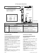
REFER TO GENERATOR WIRING DIAGRAM
FOR CONNECTION DETAILS
F2 F1 7 8 8 Z2
S1
S2
A1
A2
A
S440
Trim
Droop
Volts
Stability
Selection
UFRO
Frequency
Selection
Indicator LED
Stab
60Hz
50Hz
1
2
3
Lb
La
ABCD
Stability Selection Table
No. Power range Response
B-D < 100kW Slow
A-C < 100kW Fast
B-C 100-550kW Fast
A-B > 550kW Fast
Hand trimmer terminals. Remove
link before fitting hand trimmer.
Link must be fitted when hand
trimmer is not required.
Exc
Trip
8 and Z2 – linked for
normal operation