
Instruction Manual

DESIGN DETAIL
©2006 2 TD_AS440 AVR_03.09_04_GB
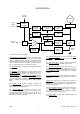
The main functions of the AVR are:
Potential Divider and Rectifier
takes a proportion of the
generator output voltage and attenuates it. The potential
divider is adjustable by the AVR Volts potentiometer and
external hand trimmer (when fitted). The output from the
droop CT is also added to this signal. A rectifier converts
the a.c. input signal into d.c. for further processing.
The DC Mixer
adds the Analogue input signal the Sensing
signal.
The Amplifier
(Amp) compares the sensing voltage to the
Reference Voltage
and amplifies the difference (error) to
provide a controlling signal for the power devices. The
Ramp Generator
and Level Detector and Driver infinitely
control the conduction period of the Power Control Devices
and hence provides the excitation system with the required
power to maintain the generator voltage within specified
limits.
The Stability Circuit
provides adjustable negative ac
feedback to ensure good steady state and transient
performance of the control system.
The Low Hz Detector
measures the period of each
electrical cycle and causes the reference voltage to be
reduced approximately linearly with speed below a
presettable threshold. A Light Emitting Diode gives
indication of underspeed running.
The Synchronising circuit is used to keep the Ramp
Generator and Low Hz Detector locked to the generator
waveform period.
The Low Pass Filter
prevents distorted waveforms
affecting the operation of the AVR control circuit.
The Short Circuit Detector
senses the presence of a
short circuit on the generator output and forces the
Power Control Devices
into full conduction. This only
occurs when the AVR is powered from an auxiliary
winding.
Power Control Devices
vary the amount of exciter field
current in response to the error signal produced by the
Amplifier.
Suppression
components are included to prevent sub
cycle voltage spikes damaging the AVR components
and also to reduce the amount of conducted noise on
the generator terminals.
The Over Excitation Detector
continuously monitors the
exciter field voltage and provides signals, to collapse
the output voltage if an over excitation condition
persists for the specified time period.
The Power Supply
provides the required voltages for
the AVR circuitry.
Suppression
Low Pass
Filte
r
Synchronising
Circuit
Low Hz
Detection
Power
Control
Devices
Level
Detector &
Driver
Reference
Volta
g
e
Stability
Circuit
Potential
Divider &
Rectifier
Power
su
pp
l
y
Ramp
Generato
r
Generator
Amp
Voltage
Sensing
Hand
Trimmer
Exciter
Field
DC
Mixe
r
Analogue
Input
Droop
Short circuit
Detecto
r
Over
excitation
detector