Tractor Drive PTO Generators OWNERS MANUAL INSTALLATION AND OPERATION INSTRUCTIONS SAFETY FIRST 35PTOC-3 40PTOC-4 45PTOC-17 50PTOC-3 55FPTOC-3 75FPTOC-4 75FPTOC-17 50PTOC-3 READ THIS MANUAL BEFORE OPERATING YOUR GENERATOR.
Read and understand all instructions in this manual before starting and operating the generator set. USING THIS MANUAL Congratulations on your choice of a Winco generator set. You have selected a high-quality, precision-engineered generator set designed and tested to give you years of satisfactory standby service. To get the best performance from your new generator set, it is important that you carefully read and follow the operating instructions in this manual.
SAFETY INFORMATION This generator set has been designed and manufactured to allow safe, reliable performance. Poor maintenance, improper or careless use can result in potential deadly hazards; from electrical shock, exhaust gas asphyxiation, or fire. Please read all safety instructions carefully before installation or use. Keep these instructions handy for future reference. Take special note and follow all warnings on the unit labels and in the manuals.
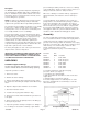
Description The WINCO PTO drive generator will provide, depending on the unit purchased, 120/240V single phase, 120/240V three phase or 120/208 three phase 60Hz electrical service when direct-driven. Tractor or vehicle power take-off shafts, can be used for driving these generators. NOTE: The prime mover which drives the generator must be capable of delivering approximately 2 HP per 1000 watts output from the generator. Observe input RPM specifications.
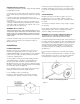
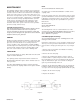
DANGER: Equipment Damage If cable-to-pin connections are loose, arcing and heat damage to equipment can result. 5. Insert the brass pin (with cable) into the plug body, and line up the retainer pin holes in the brass pin with those in the plug body. 6. Insert the retainer pin, and tap it firmly into place. The retainer pin will protrude approximately 3/8" when fully seated. (See Figure 1.) 7. Repeat steps 4 through 6 for each brass pin.
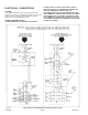
ELECTRICAL CONNECTIONS CAUTION: Only qualified electricians should install electrical wiring. Wiring must conform to all applicable national, state, and local codes. (Reference: National Fire Protection Association Manual No. 70, National Electrical Code.) DANGER: PERSONAL INJURY POWER SOURCE, A SPECIAL DISCONNECT SWITCH MUST BE INSTALLED TO SEPARATE THE GENERATOR AND THE COMMERCIAL POWER LINES.
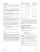
MOTOR LOAD Motor Horsepower Operation OUTPUT POWER AVAILABLE AND LOAD DETERMINATION Before using the generator, read and understand the following information. Generator output current (amperage) is internally limited by three circuit breakers. If too much demand is placed on a generator output (if you try to drive too many motors with it, for example), one of the circuit breakers will trip, cutting off the output in order to protect the generator.
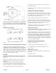
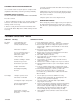
energized by the generator. Make sure the connections are correct and are tight. 8. Make sure all loads are turned off. Do not start the generator under load. GENERATOR STARTING PROCEDURE 1. With the power take-off drive disengaged, start the engine which will drive the generator. Run the engine long enough to warm it up before proceeding, so that it will run smoothly and achieve full power under generator load. 2. With engine idling, engage the power take-off drive. Figure 6 3.
NOTE: Do not over lubricate the universal joints. MAINTENANCE The following chart lists various symptoms of poor generator operation with possible causes for them and the appropriate corrective action. You will need a volt-ohm meter or test light to check some of the causes. For some of the other causes you will need to check generator speed. To check generator speed you can use a frequency meter, a tachometer, or a 120V-60Hz electric clock and a correctly operating wrist watch.
CLEANING & INSPECTING THE GENERATOR 3. Vacuum or blow dust and other debris from inside generator and control box. Use a vacuum cleaner or dry low pressure compressed air (regulated at 25-35 PSI) to clean the generator periodically. 4. With panel cover removed, inspect the brushes for wear, and inspect the wiring for correct routing, fraying insulation, and secure connections. WARNING: Equipment Damage DO NOT CLEAN THE GENERATOR WHILE IT IS RUNNING. 5. Replace panel cover and cooling fan shroud.
SYMPTOM CAUSE(S) CORRECTIVE ACTION High voltage. 1. Engine speed too fast. 2. Connection of current transformer secondary leads not correct. 1. 2. Check engine speed for correct input RPM. Have qualified service technician recheck the connections. Output voltage flickering or fluctuation. 1. Tumbling bar (coupling shaft) misalignment. 2. Engine speed not constant. 1. Reduce tumbling bar misalignment to less than 15 degrees. 2. Excessive vibration. 3. Loose connection in field circuit. 4.
WINCO PTO GENERATORS 36 MONTH LIMITED WARRANTY WINCO, Inc., warrants for thirty-six months from date of shipment, that it will repair or replace at its option, for the original user, the whole or any part of the product found upon examination, by WINCO at its factory at 225 South Cordova Avenue, Le Center, Minnesota, or by any factory-authorized service station, to be defective in material or workmanship under normal standby use (average less than 50 hours per month) and service.