Tractor Drive PTO Generators OWNERS MANUAL INSTALLATION AND OPERATION INSTRUCTIONS 35PTOC-3 40PTOC-4 45PTOC-17 50PTOC-3 75FPTOC-4 75FPTOC-17 75FPTOC-17 SAFETY FIRST READ THIS MANUAL BEFORE OPERATING YOUR GENERATOR.
Read and understand all instructions in this manual before starting and operating the generator set. USING THIS MANUAL Congratulations on your choice of a Winco generator set. You have selected a high-quality, precision-engineered generator set designed and tested to give you years of satisfactory standby service. To get the best performance from your new generator set, it is important that you carefully read and follow the operating instructions in this manual.
. SAFETY INFORMATION This generator set has been designed and manufactured to allow safe, reliable performance. Poor maintenance, improper or careless use can result in potential deadly hazards; from electrical shock, exhaust gas asphyxiation, or fire. Please read all safety instructions carefully before installation or use. Keep these instructions handy for future reference. Take special note and follow all warnings on the unit labels and in the manuals. a. b. 4. b.
Description The WINCO PTO drive generator will provide, depending on the unit purchased, 120/240V single phase, 120/240V three phase or 120/208 three phase 60Hz electrical service when direct-driven. Tractor or vehicle power take-off shafts, can be used for driving these generators. NOTE: The prime mover which drives the generator must be capable of delivering approximately 2 HP per 1000 watts output from the generator. Observe input RPM specifications.
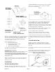
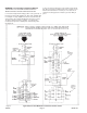
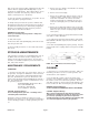
WIRE INSERTS NOT USED IN ALL APPLICATIONS “TRAILER MOUNTING” if generator will be used as a portable power source (see Figure 3). When planning a foundation consider the following points: Figure 2 CONTACTS All 4 contact must be used. SINGLE PHASE 4 WIRE CONNECTION A. The foundation location should enable aligning the drive shaft (tumbling bar) in a straight or nearly straight line between the power take-off and the generator input shaft.
WARNING: Personal Injury & Equipment Damage TRAILER MAY TIP OVER AND CAUSE INJURIES IF WHEELS ARE NOT SPACED FAR ENOUGH APART. C. The trailer height and mounting position of the generator on the trailer should enable aligning the drive shaft (tumbling bar) in a straight or nearly straight line between the power take-off and generator input shafts. Misalignment must be less than 15 degrees during generator operation, even though the mechanical design of the tumbling bar would allow greater misalignment.
ELECTRICAL CONNECTIONS CAUTION: Only qualified electricians should install electrical wiring. Wiring must conform to all applicable national, state, and local codes. (Reference: National Fire Protection Association Manual No. 70, National Electrical Code.) DANGER: PERSONAL INJURY IF THE GENERATOR IS TO BE USED AS A STANDBY POWER SOURCE, A SPECIAL DISCONNECT SWITCH MUST BE INSTALLED TO SEPARATE THE GENERATOR AND THE COMMERCIAL POWER LINES.
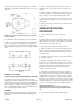
2. Check gear case oil level. (See Figure 6.) Case should be filled with oil to plug marked “OIL LEVEL.” Fill or remove oil as required. 5. Make sure no binding exists in generator or gear box. If binding is found, locate the cause and correct it before proceeding. 6. Make sure that the electrical loads to be driven by the generator will not draw more current than the ratings of the generator receptacle or cord set which will supply the current. 7.
lamp on the front of transfer switch; (applicable only when the transfer switch is equipped with indicating lamps or your electrician has installed them). After sufficient time to assure that power restoration isn’t temporary, return the transfer switch to normal power (10 - 20 minutes). a. Remove gear case breather. Soak breather in cleaning solvent, then allow it to dry. b. Remove oil level check plug. c. Remove the oil drain plug, drain the oil into a clean oil resistant container, 1 quart or larger.
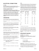
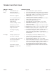
TROUBLE SHOOTING TABLE SYMPTOM No output voltage. CAUSE(S) CORRECTIVE ACTION 1. Circuit breaker open. 2. Defective voltmeter. 3. Short circuit in the load. 4. Defective receptacles. 5. Loose (or broken) wires or connections in control box. 6. Defective rectifier. 7. Dirty slip rings. 8. Brushes binding in holders. 9. Shorted or open rotor. 10.Shorted or open stator. 11.Open transformer. 12.Rotating field polarity incorrect. Low voltage. 1004-00 1. 2. 3. Reset circuit breakers, replace if defective.
SYMPTOM CAUSE(S) CORRECTIVE ACTION High voltage. 1. Engine speed too fast. 2. Connection of current transformer secondary leads not correct. 1. 2. Check engine speed for correct input RPM. Have qualified service technician recheck the connections. Output voltage flickering or fluctuation. 1. Tumbling bar (coupling shaft) misalignment. 2. Engine speed not constant. 1. Reduce tumbling bar misalignment to less than 15 degrees. 2. Excessive vibration. 3. Loose connection in field circuit. 4.
WINCO PTO GENERATORS 36 MONTH LIMITED WARRANTY WINCO, Inc., warrants for thirty-six months from date of shipment, that it will repair or replace at its option, for the original user, the whole or any part of the product found upon examination, by WINCO at its factory at 225 South Cordova Avenue, Le Center, Minnesota, or by any factory-authorized service station, to be defective in material or workmanship under normal standby use (average less than 50 hours per month) and service.