
Installation Guide


1190828-UIM-G-0915
Johnson Controls Unitary Products 7
SECTION VI: LINE POWER CONNECTIONS
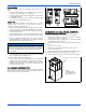
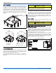
Power may be brought into the unit through the supply air end of the
unit (top left when unit is vertical) or the left side panel. Use the hole
appropriate to the unit’s orientation in each installation to bring conduit
from the disconnect. The power lead conduit should be terminated at
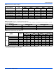
the electrical control box. Refer to Tables 3, 8 and 9 to determine
proper wire sizing. Refer to the latest edition of the National Electric
Code or in Canada the Canadian electrical Code and local codes to
determine correct wire sizing. To minimize air leakage, seal the wiring
entry point at the outside of the unit.
All electrical connections to air handlers must be made with copper
conductors. Direct connection of aluminum wiring to air handlers is
not approved.
If aluminum conductors are present, all applicable local and national
codes must be followed when converting from aluminum to copper
conductors prior to connection to the air handler.
The chosen conductor and connections all must meet or exceed the
amperage rating of the overcurrent protector (service disconnect or
fuse) in the circuit.
Additionally, existing aluminum wire within the structure must be sized
correctly for the application according to National Electric Code and
local codes. Caution must be used when sizing aluminum rather than
copper conductors, as aluminum conductors are rated for less current
than copper conductors of the same size.
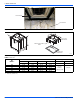
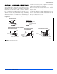
FIGURE 10: Line Power Connections
GND.
FIELD POWER WIRING
(208/230V)
NO ELECTRIC HEAT
COMPONENT CODES
CKT - CIRCUIT
CN - WIRE CONNECTOR/NUT
GND - GROUND LUG
SD - SERVICE DISCONNECT
POWER
SUPPLY
CN
CN
GND
JUMPER BAR
SINGLE SOURCE POWER
MULTI-SOURCE POWERSINGLE-SOURCE POWER
WITH JUMPER BAR
TERMINAL BLOCK OR
SERVICE DISCONNECT
POWER
SUPPLY
POWER
SUPPLY
2 CIRCUITS ON 13KW-20KW
SD
SD
POWER
SUPPLY
GND
GND
L1
L2
L1
L2
L1
L2
L1
L2
SD
SD
CKT 2
CKT 1
SINGLE PHASE ELECTRIC HEAT OPTIONS:
2 CIRCUITS ON 13KW-20KW
A0429-001