
Installation Guide
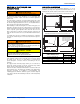


1190828-UIM-G-0915
8 Johnson Controls Unitary Products
SECTION VII: LOW VOLTAGE CONTROL
CONNECTIONS
The 24 volt power supply is provided by an internally wired low voltage
transformer which is standard on all models. if the unit is connected to a
208 volt power supply, the low voltage transformer must be rewired to
the 208 volt tap. See the unit wiring diagram.
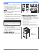
Field supplied low voltage wiring can exit the unit through the top right
(when unit is vertical upflow) or the right side panel. Refer to Figure 5.
Remove desired knockout and pierce foil faced insulation to allow
wiring to pass through. Use as small of a hole as possible to minimize
air leakage. Install a 7/8” plastic bushing in the selected hole and keep
low voltage wiring as short as possible inside the control box.
To further minimize air leakage, seal the wiring entry point at the
outside of the unit.
The field wiring is to be connected at the pigtails supplied with the air
handler. Refer to Figures 13 and 14 for system wiring.
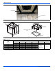
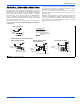
SECTION VIII: BLOWER SPEED
CONNECTIONS
Adjust blower motor speed to provide airflow within the minimum and
maximum limits approved for indoor coil, electric heat and outdoor unit.
Speed tap adjustments are made at the motor terminal block. Airflow
data is shown in Table 10.
Connect motor wires to motor speed tap receptacle for speed desired.
See unit wiring label for motor wiring details.
Blower Speed Connections
SECTION IX: UNIT DATA
NOTICE
All wiring must comply with local and national electrical code require-
ments. Read and heed all unit caution labels.
NOTICE
It is possible to vary the amount of electric heat turned on during the
defrost cycle of a heat pump. Standard wiring will only bring on the
first stage of electric heat during defrost. See Table 7 for additional
information on heat during defrost cycle.
FIGURE 11: Blower Speed Connections
FACTORY WIRED TO
TRANSFORMER
FACTORY WIRED TO
FAN MOTOR RELAY
TERMINAL ON
CONTROLBOARD
PUR
PUR
HIGH
MED
LOW
GND.
230 VOLT
BLOWER MOTOR
CAP
BRN
BLK
A0342-001
PSC STANDARD MOTOR
FACTORY WIRED TO
TRANSFORMER
FACTORY WIRED TO
FAN MOTOR RELAY
TERMINAL ON
CONTROLBOARD
PSC STANDARD MOTOR
ALTERNATE CONNECTION
AP60, RFCX60, MP20
ALL OTHER AIR HANDLER
GND.
CAP
BRN
BLK
H M L
RC
PRP
PRP
230 VOLT
BLOWER
MOTOR
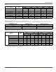
TABLE 2:
Physical and Electrical Data - Cooling Only
Models MP08B MP12B MP14D MP16C MP20D
Blower - Diameter x Width
10 x 8 10 x 8 10 x 10 10 x 10 10 x 10
Motor
HP
1/4 HP 1/2 HP 1/2 HP 1/2 HP 1 HP
Nominal RPM
850 1085 1085 1040 1007
Voltage
208/230 208/230 208/230 208/230 208/230
Full Load Amps @230V
1.4 2.6 2.8 2.9 4.1
Filter
1
Type DISPOSABLE OR PERMANENT
Size
16 x 20 x 1 16 x 20 x 1 22 x 20 x 1 20 x 20 x 1 22 x 20 x 1
Bottom Rack Kit
1BR01117 1BR01117 1BR01124 1BR01121 1BR01124
Permanent Type Kit
1PF0601 1PF0601 1PF0603 1PF0602 1PF0603
Shipping / Operating Weight (lbs.)
52/51 52/51 75/74 68/67 75/74
1. Field supplied.
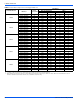
TABLE 3:
Electrical Data - Cooling Only
Models
Motor FLA
1
Minimum Circuit Ampacity
MOP
2
MP08B 1.4 1.8 15
MP12B 2.6 3.3 15
MP14D 2.8 3.5 15
MP16C 2.9 3.6 15
MP20D 4.1 5.1 15
1. FLA = Full Load Amps
2. MOP = Maximum Overcurrent Protection device; must be HACR type service disconnect or time delay fuse. Refer to the latest edition of the National Electric Code or in Canada
the Canadian electrical Code and local codes to determine correct wire sizing.