
Installation Guide


1190828-UIM-G-0915
6 Johnson Controls Unitary Products
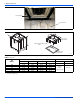
DUCT FLANGES
Three duct flanges are provided to assist in positioning and attaching
duct work to the air handler. These flanges are included in the unit parts
bag. With the screws from the parts bag, install one of the duct flanges.
Duct flanges have holes on both legs with one leg longer than the other.
The longer leg can be used to mate against the air handler so that
different thicknesses of duct board can be made flush with the outer
surface of the air handler. Repeat the procedure for the other two
flanges. Refer to Figure 7. If the flanges are not used, they may be
discarded.
UNIT CONNECTIONS
There are several ways to handle the supply and return air duct
connections. The location and sizing of the connections depends on the
situation and the method best suited to the installation. Upflow,
horizontal or downflow applications may be used.
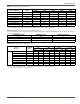
The supply air duct should be properly sized by use of a transition to
match unit opening. Refer to Table 1 for air handler unit inlet and outlet
dimensions.
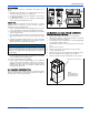
Duct work that is not designed to match the supply air opening can
cause turbulence inside the plenum. This turbulence can change the air
flow patterns across the electric heater limit switches. If the factory
suggested transition cannot be fabricated, it is recommended that a
block off plate (approximately 8" high and running the full width of the
plenum) be attached to the supply opening. Refer to Figure 8 as a
visual aid. The use of this block off plate will enable better air circulation
across the limit switches.
AIR FILTERS
Return air filters are required and must be field supplied. Filtration must
be accomplished external to the unit.
.
SECTION V: ELECTRIC HEATER
INSTALLATION
If the air handler requires electric heat, install the electric heat kit
according to the installation instructions included with the kit. After
installing the kit, mark the air handler nameplate to designate the heater
kit that was installed. If no heater is installed, mark the name plate
appropriately to indicate that no heat kit is installed.
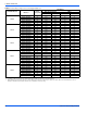
Use only 6HK Revision C or later heater kits, as listed on air handler
name plate and in these instructions. Use data from Tables 4 through 9
for information on required minimum motor speed tap to be used for
heating operation, maximum over-current protection device required as
listed for combination of air handler and heater kit.
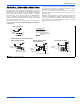
FIGURE 7: Duct Attachment
FIGURE 8: Duct Work Transition
A0445-001
DUCT FLANGES
(Shipped in bag with unit)
A0332-001
RECOMMENDED
TRANSITION
SUGGESTED LOCATION
OF BLOCK OFF PLATE
CAUTION
Use 1/2” screws to connect duct work to unit. Longer screws will
pierce the drain pan and cause leakage. If pilot holes are drilled, drill
only though field duct and unit bottom duct flange.
CAUTION
Equipment should never be operated without filters.
FIGURE 9: Blower Delay Control Board
!
!
PSC CONTROLBOARD
A0356-001