
Installation Guide


1190828-UIM-G-0915
Johnson Controls Unitary Products 5
SECTION IV: DUCT WORK AND
CONNECTIONS
Air supply and return may be handled in one of several ways best
suited to the installation. Upflow, horizontal or downflow applications
may be used.
The vast majority of problems encountered with heating and cooling
systems can be linked to improperly designed or installed duct systems.
It is therefore highly important to the success of an installation that the
duct system be properly designed and installed.
When installing a central air return grille in or near the living space, it is
advisable to design the duct work so that the grille is not in direct line
with the opening in the unit. One or two elbows and acoustical duct liner
assures a quieter system. Operation where return air duct is short or
where sound may be a problem, acoustical duct liner should be used
inside the duct. If electric heat is used, non-flammable material must be
used.
Use flexible duct connectors to minimize the transmission of vibration/
noise into the conditioned space. Never fasten duct work directly to the
structure.
Insulation of duct work is a must where it runs through an unheated
space during the heating season or through an uncooled space during
the cooling season. The use of a vapor barrier is recommended to
prevent absorption of moisture from the surrounding air into the
insulation.
The supply air duct should be properly sized by use of a transition to
match unit opening. All ducts should be suspended using flexible
hangers and never fastened directly to the structure.
Duct work should be fabricated and installed in accordance with local
and/or national codes. This includes the standards of the National Fire
Protection Association for Installation of Air-Conditioning and
Ventilating Systems, NFPA No. 90B. Duct systems should be designed
in accordance with the Air Conditioning Contractors of America (ACCA)
– Manual D.
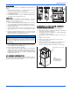
HORIZONTAL SUSPENSION
For suspension of these units in horizontal applications, it is recom-
mended to use angle steel support brackets with threaded rods, sup-
porting the units from the bottom, at the locations shown in Figure 6.
WARNING
Use only 1/2” screws to connect duct work to bottom of unit.
WARNING
Do not bring in return air from a location which could introduce haz-
ardous substances into the airflow.
Use 1/2” screws to connect duct work to cabinet. If pilot holes are
drilled, drill only through field duct and unit flange.
CAUTION
This unit is not designed for non-ducted (freeblow) applications. Do
not operate without duct work attached to unit.
Equipment should never be operated without filters.
!
!
!
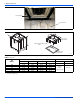
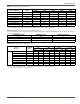
(Cabinet Width) Position
Dimensions
HX
(17-1/2”) Horizontal Left 40-1/2” – 47-1/2” 20”
(21” thru 24-1/2”) Horizontal Left 43-1/2” – 55-1/2” 21”
(17-1/2”) Horizontal Right 40-1/2” – 47-1/2” 20”
(21” thru 24-1/2”) Horizontal Right 43-1/2” – 55-1/2” 21”
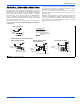
FIGURE 6: Typical Horizontal Installation
SUSPENSION SUPPORT LOCATIONS FOR HORIZONTAL RIGHT
2”
1-1/2”
MIN. 1-1/2” x 1-1/2”
Angle Recommended
length 26” minimum
with 2” clearance on both
sides of Air Handler
MIN. 3/8”
THREADED ROD
H
1”
1-1/2”
A0348-002
X
H
SUSPENSION SUPPORT LOCATIONS FOR HORIZONTAL LEFT
X
TIE PLATE