
Installation Guide


1190828-UIM-G-0915
Johnson Controls Unitary Products 3
CLEARANCES
Clearances must be taken into consideration, and provided for as
follows:
1. Maintenance and servicing access - minimum 36” from front of unit
recommended for blower motor / coil replacement.
2. The duct work connected to this unit is designed for zero clearance
to combustible materials.
3. A combustible floor base accessory is available for downflow appli-
cations of this unit, if required by local code.
LOCATION
Location is usually predetermined. Check with owner’s or dealer’s
installation plans. If location has not been decided, consider the
following in choosing a suitable location:
1. Select a location with adequate structural support, space for service
access, and clearance for air return and supply duct connections.
2. Using hanging brackets to wall mount this single piece air handler
unit is not recommended.
3. Normal operating sound levels may be objectionable if the air han-
dler is placed directly over some rooms such as bedrooms, study,
etc.
4. If using the air handler unit with an indoor coil, select a location that
will permit installation of condensate line to open drain or outdoors
allowing condensate to drain away from structure.
5. When an indoor coil is installed in an attic or above a finished ceil-
ing, an auxiliary drain pan should be provided under the air handler
as is specified by most local building codes.
6. Proper electrical supply must be available.
7. If unit is located in an area of high humidity (i.e. an unconditioned
garage or attic), nuisance sweating of casing may occur. On these
installations, unit duct connections and other openings should be
properly sealed, and a wrap of 2” fiberglass insulation with vinyl
vapor barrier should be used.
AIR HANDLER CONFIGURATION
These air handler units are supplied ready to be installed in an upflow,
downflow, horizontal right or horizontal left position. Refer to Figure 2.
The unit requires no conversion procedures.
AIR HANDLER AND COIL UPFLOW, DOWNFLOW,
AND HORIZONTAL POSTIONS
1. Apply neoprene gasket to the return air end of air handler.
2. Attach three tie plates to external sides and back of air handler
casing using screws. Refer to Figure 3.
3. Position blower casing over appropriate coil opening (depending
on configuration). Refer to Figure 2.
4. Attach the three tie plates to coil casing using screws. Refer to Fig-
ure 3.
5. Remove coil access panel.
6. Slide the coil out of the coil cabinet, and set coil to the side.
7. Locate 2” wide foam gasket.
8. Apply foam gasket over the air handler and coil mating seams on
the interior of both unit sides and back. Refer to Figure 4.
9. Slide the coil into the housing, and install the coil access panel.
NOTICE
The primary and secondary drain line must be trapped to allow proper
drainage of condensate water. The secondary drain line should be
piped to a location that will give the occupant a visual warning that the
primary drain is clogged. If the secondary drain line is not used, it
must be capped.
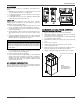
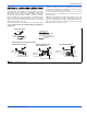
FIGURE 2: Typical Installation
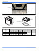
FIGURE 3: Coil and Air Handler Attachment Details
A0346-001
UPFLOW
DOWNFLOW
HORIZONTAL RIGHT
HEAT
HORIZONTAL LEFT
HEAT
HEAT
HEAT
HEAT
A0347-001
OUTER TIE PLATE (3 PLACES)
AIR
HANDLER
COIL
NOTE:
External tie plates
are installed on both
sides and the back