
Installation Guide

5594752-UIM-B-0419
Johnson Controls Ducted Systems 13
ACCESSORY CONNECTIONS
The furnace control will allow power-switching control of various acces-
sories.
ELECTRONIC AIR CLEANER CONNECTION
Two 1/4” (6.4 mm) spade terminals (EAC and NEUTRAL) for electronic
air cleaner connections are located on the control board. The terminals
provide 115VAC (1.0 Amp maximum) during circulating blower opera-
tion.
HUMIDIFIER CONNECTION
Two 1/4” (6.4 mm) spade terminals (HUM and NEUTRAL) for humidifier
connections are located on the control board. The terminals provide
115VAC (1.0 Amp maximum) during heating system operation.
A mounting hole is provided on the control panel next to the furnace
control board for mounting a humidifier transformer if required.
TWINNING
These furnaces may be twinned only if a field-supplied twinning kit is
used. The twinning kit must be designed and approved for use with
these furnaces. Follow the instructions supplied with the twinning kit for
details of electrical connections.
SECTION VI: VENT SYSTEM
VENT CONNECTIONS
All models are provided with a flue transition that is sized for 4” diame-
ter vent connections. If a larger size vent connector is required, that
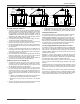
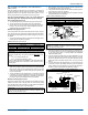
connection must be installed external to the furnace. Figure 14 shows
the furnace as it is shipped from the factory. To convert to a horizontal
or downflow position, remove the four screws that secure the inducer
assembly and rotate 90º being careful not to damage the gasket. Rein-
stall screws. Remove cap from appropriate vent outlet location on the
cabinet, cut insulation in cabinet to same size as the hole provided and
reinstall cap in the hole in the top panel.
CATEGORY 1 - 450 F. MAX. VENT TEMP.
The venting system must be installed in accordance with Section 5.3,
Air for Combustion and Ventilation, of the National Fuel Gas Code
Z223.1/NFPA 54 (latest edition), or Sections 7.2, 7.3 or 7.4 of CSA
B149.1, National Gas and Propane Codes (latest edition) or applicable
provisions of the local building code and these instructions.
The furnace shall be connected to any type of B, BW or L vent connec-
tor, and shall be connected to a factory-built or masonry chimney. The
furnace shall not be connected to a chimney flue serving a sepa-
rate appliance designed to burn solid fuel.
It is recommended that the appliance is installed in a location where the
space temperature is 32ºF (0ºC) or higher. If the appliance is installed in
a location where the ambient temperature is below 32ºF (0ºC), the com-
bustion byproducts could condense causing damage to the appliance
heat exchanger.
This appliance may be common vented with another gas appliance for
residential installations as allowed by the codes and standards listed in
these instructions.
Non-HUD approved Modular Homes must be vented with an approved
roof jack and may not be common vented with other appliances.
VENTING
Category I venting consists of vertically venting one or more appliances
in B-vent or masonry chimney (as allowed), using single wall metal pipe
or B-vent connectors. Type B-vent system extends in a general vertical
direction and does not contain offsets exceeding 45º. A vent system
having not more than one 60º offset is permitted.
VENTING INTO AN EXISTING CHIMNEY
For Category I installations, the furnace shall be connected to a factory
built chimney or vent complying with a recognized standard, or a
masonry or concrete chimney lined with a material acceptable to the
authority having jurisdiction. Venting into an unlined masonry chimney
or concrete chimney is prohibited.
Where use of an existing chimney is unavoidable, the following rules
must be followed:
1. The masonry chimney must be built and installed in accordance
with nationally recognized building codes or standards and must be
lined with approved fire clay tile flue liners or other approved liner
material that will resist corrosion, softening, or cracking from flue
gases. THIS FURNACE IS NOT TO BE VENTED INTO AN
UNLINED MASONRY CHIMNEY.
2. This furnace must be vented into a fire clay tile lined masonry chim-
ney only if a source of dilution air is provided, such as by common
venting with a draft hood equipped water heater. If no source of
dilution air is available, Type B vent must be used, or masonry
chimney vent kit S1-1CK0604 must be used. Refer to the instruc-
tions with the kit to properly apply these masonry chimney kits.
3. The chimney must extend at least 3 ft (91 cm) above the highest
point where it passes through a roof of a building and at least two
feet higher than any portion of the building with a horizontal dis-
tance of ten feet.
4. The chimney must extend at least 5 ft (1.5 m) above the highest
equipment draft hood or flue collar.
FAN-ASSISTED COMBUSTION SYSTEM
This appliance is equipped with an integral mechanical means to either
draw products of combustion through the heat exchanger.
Ambient Combustion Air Supply
This type installation will draw the air required for combustion from
within the space surrounding the appliance and from areas or rooms
adjacent to the space surrounding the appliance. This may be from
within the space in a non-confined location or it may be brought into the
furnace area from outdoors through permanent openings or ducts. A
single, properly sized pipe from the furnace vent connector to the out-
doors must be provided. Combustion air is brought into the furnace
through the unit top panel opening.
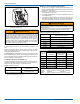
IMPORTANT: In downflow applications, do not block the combustion
air inlet. The furnace must be installed on a coil cabinet or subbase to
allow combustion air to enter the burner compartment.
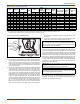
FIGURE 14: Combustion Air Inducer
COMBUSTION AIR INDUCER
90° 90°
Mounting Screw
(Remove)
Flue Transition
(Do Not Remove)
Mounting Screw
(Remove)
Pressure
Switch
Pressure Switch
Tube Routing