
Specification

5597959-BTG-A-0119
Johnson Controls Unitary Products 3
Annual Fuel Utilization Efficiency (AFUE) numbers are determined in accordance with DOE Test procedures.
Wire size and over current protection must comply with the National Electrical Code (NFPA-70-latest edition) and all local codes.
The furnace shall be installed so that the electrical components are protected from water.
HORIZONTAL SIDEWALL VENTING
For applications where vertical venting is not possible, the only
approved method of horizontal venting is the use of an auxiliary
power vent. Auxiliary power venters must be approved by CSA,
UL, or other recognized safety agencies. Follow all application
and installation details provided by the manufacturer of the
power vent.
FILTER PERFORMANCE
The airflow capacity data published in the “Blower Perfor-
mance” table shown represents blower performance WITHOUT
filters.
All applications of these furnaces require the use of field
installed air filters. All filter media and mounting hardware or
provisions must be field installed external to the furnace cabi-
net. DO NOT attempt to install any filters inside the furnace.
1. Air velocity through throwaway type filters may not exceed 300 feet per min-
ute (91.4 m/min). All velocities over this require the use of high velocity fil-
ters.
2. Do not exceed 1800 CFM using a single side return and a 16x25 filter. For
CFM greater than 1800, you may use two side returns or one side and the
bottom or one return with a transition to allow use of a 20x25 filter.
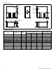
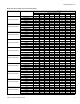
Ratings & Physical / Electrical Data
Models
Input Output
AFUE
Air Temp.
Rise
Max. Outlet
Air Temp
Blower
Blower
Size
Recommended
Fuse or Circuit
Breaker Amps
Total Unit
Amps
Gas Pipe
Connection,
NPT
MBH MBH °F °F HP Amps
TM(8,L)E040A12MP11 40 32 80.0 20-50 190 1/2 6.4 11 x 8 15 8.2 1/2"
TM(8,L)E060A12MP11 60 48 80.0 30-60 190 1/2 6.4 11 x 8 15 8.2 1/2"
TM(8,L)E080B12MP11 80 64 80.0 35-65 190 1/2 6.4 11 x 8 15 8.7 1/2"
TM(8,L)E080C16MP11 80 64 80.0 30-60 190 1/2 6.4 11 x 10 15 8.7 1/2"
TM(8,L)E080C20MP11 80 64 80.0 25-55 190 1 11.5 11 x 11 20 13.8 1/2"
TM(8,L)E100B12MP11 100 80 80.0 40-70 190 1/2 6.4 11 x 8 15 8.7 1/2"
TM(8,L)E100C16MP11 100 80 80.0 40-70 190 3/4 8.8 11 x 10 15 11.1 1/2"
TM(8,L)E100C20MP11 100 80 80.0 25-55 190 1 11.5 11 x 11 20 13.8 1/2"
TM(8,L)E120C16MP11 120 96 80.0 40-70 190 3/4 8.8 11 x 10 15 11.1 1/2"
TM(8,L)E120C20MP11 120 96 80.0 35-65 190 1 11.5 11 x 11 20 13.7 1/2"
TM(8,L)E130D20MP11 130 104 80.0 35-65 190 1 11.5 11 x 11 20 13.7 1/2"
CAUTION
In downflow furnace arrangement, the filter must be located
a minimum of 12” from the return air inlet of furnace.
!
NOTICE
Single side return above 1800 CFM is approved as long as
the filter velocity does not exceed filter manufacturer’s rec-
ommendation and a transition is used to allow use on a
20x25 filter.
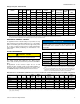
Recommended Filter Sizes
CFM (m
3
/min)
Cabinet
Size
Side
(in)
Bottom
(in)
1200 (34.0) A 16 x 25 14 x 25
1200 (34.0) B 16 x 25 16 x 25
1600 (45.3) C 16 x 25 20 x 25
2000 (56.6) C (2) 16 x 25 20 x 25
2000 (56.6) D (2) 16 x 25 22 x 25
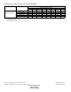
Unit Clearances to Combustibles (All dimensions in inches, and all surfaces identified with the unit in an upflow configuration)
Application Top Front Rear
Left
Side
Right
Side
Flue
Floor/
Bottom
Closet Alcove Attic
Line
Contact
Upflow 1 6 0 0 3 6 Combustible Yes Yes Yes No
Upflow B-Vent 1 3 0 0 0 1 Combustible Yes Yes Yes No
Downflow 1 6 0 0 3 6
1
1
1. Special floor base or air conditioning coil required for use on combustible floor.
Yes Yes Yes No
Downflow B-Vent 1 3 0 0 0 1
1
1
Yes Yes Yes No
Horizontal 1 6 0 0 3 6 Combustible No Yes Yes
Yes
2
2. Line contact only permitted between lines formed by the intersection of the rear panel and side panel (top in horizontal position) of the furnace jacket and building
joists, studs, or framing.
Horizontal B-Vent 1 3 0 0 0 1 Combustible No Yes Yes
Yes
2