
Owner`s manual
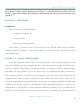

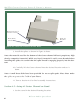


3. Install the spikes as shown in Figure 9 above.
Note: the material used for the bottom of the Center channel Wilson’s proprietary high
density composite X-material. While very hard, X-material is easily cross threaded when
installing the spikes. Be careful that the spike thread is engaging properly into the bot-
tom.
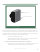
10. Carefully lift the Center channel into the desired location and set it
down.
Note: 4 small brass disks have been provided for use as spike pads. Place these under
the spikes to protect the finish of your floors.
11. Turn to Section 4.8 for final assembly instructions.
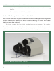
Section 4.5—Setup #2 Center Channel on Stand
1. Set the stand in the desired listening location.
Fi gu re 9 - in STAllin g T He SPi ke S
SpacerS (uSe Only if
indicated in table)
SpiKe and
nut Only
diOde, SpiKe,
and nut
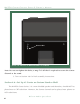
Fi gu re 10 – inSTAlli ng THe Ce nTer CHA nne l SPi keS
W A T C H C e n T e r C H A n n e l S e r i e S 3 O W n e r ’ S M A n u A l
46
Wilson Audio Specialties