
Owner`s manual


position. This will allow the Center channel to take advantage of the propagation delay
correction technology (PDC). Simply placing the Center in a location without following the
directions below will hinder the performance of the Center channel. With the correct PDC
you will find the vocals and dialogue more realistic and satisfying. As with any component
in your system that offers increased resolution and detail, a careful setup is required.
There are four different setup procedures depending on your Center channel location.
The possible Center channel configurations are as follows:
Section 4.4—Setup #1 Center Channel on Floor
Section 4.5—Setup #2 Center Channel on Stand
Section 4.6—Setup #3 Center Channel on Custom Stand or Shelf
Section 4.7—Setup #4 Center Channel on Ceiling
Please proceed to the indicated section for your particular installation for detailed
setup instructions.
Section 4.4—Setup #1 Center Channel on Floor
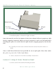
The floor mounted Center channel must be rotated up toward the listening position.
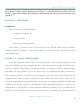
This is done by using a taller spike in the front than in the back of the speaker (see Figure 9).
The default rotation is set by using a combination of a spike, nut, and a diode. If required,
additional rotation can be achieved by using the provided 1/2” spacers between the diode
and the bottom of the cabinet (see Figure 7). The amount of rotation depends on your lis-
tening position.
Set the rotation as follows:
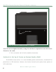
1. Using provided 3/16 Allen wrench, remove the back two setscrews from the
bottom of the Center channel. Insert the spike with nut in their place. Turn
to Section 10, table 1, locate your listening position on the table.
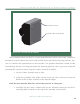
2. Assemble the front spikes with the listed diode/spacer combination in Table
1 (see also Figure 7).
S e C T i O n 4 . 4 — S e T u P # 1 C e n T e r C H a n n e l O n f l O O r
45
Wilson Audio Specialties