
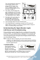
User's Manual


Signal Booster Specifications
Channelized 800 Channelized 1900
Model Number 277180 277380
Antenna connectors N Type N Type
Antenna impedance 50 Ohms 50 Ohms
Dimensions 6.75 x 4 x 1.3 inch (17.1 x 10.2 x 3.3 cm) 6.75 x 4 x 1.3 inch (17.1 x 10.2 x 3.3 cm)
Weight 1.29 lbs (.585 kg) 1.29 lbs (.585 kg)
Frequency 824-894 MHz 1850-1990 MHz
1
Channels Passband Gain (nominal)
800 MHz
Typical / Maximum
1900 MHz
Typical / Maximum
70 dB / 75 dB 71 dB / 78 dB
2
20 dB Bandwidth (nominal)
800 MHz
Typical / Maximum
1900 MHz
Typical / Maximum
12 MHz / 14 MHz 16 MHz / 18 MHz
3
Power output for single cell phone (uplink) dBm 800 MHz 1900 MHz
CDMA 29.7 30.3
EDGE 29.1 29.8
GSM 29.3 30.0
WCDMA 29.8 30.7
3
Power output for single cell phone (downlink) dBm
800 MHz 1900 MHz
CDMA 29.8 29.8
EDGE 29.5 28.8
GSM 29.3 29.7
WCDMA 29.8 30.9
3
Power output for multiple transmitted signals
(uplink) dBm Maximum Power
The maximum power is reduced
by the number of signals:
Number of signals 800 MHz 1900 MHz
2 23.3 22.8
3 18.3 19.2
4 17.2 16.7
5 15.3 14.8
6 13.7 13.2
4
Power output for multiple received signals
(downlink) dBm Maximum Power
The maximum power is reduced
by the number of signals:
Number of signals 800 MHz 1900 MHz
2 24.1 24.2
3 18.3 20.7
4 18.1 18.2
5 16.2 16.3
6 14.6 14.7
Noise Figure (typical downlink/uplink) 3.5 dB nominal 3.5 dB nominal
Isolation > 90 dB > 90 dB
Power Requirements 110-240 V AC, 50-60 Hz, 15 W 110-240 V AC, 50-60 Hz, 15 W
Notes:
1. Nominal gain is the maximum gain at any frequency in the passband.
2. Nominal bandwidth is the difference between two frequencies that are adjacent to the passband where the amplification is 20 dB lower than the passband
amplification. One of the frequencies is lower than the passband and the other is higher.
3. The Manufacturer’s rated output power of this equipment is for single carrier operation. For situations when multiple carrier signals are present, the
rating would have to be reduced by 3.5 dB, especially where the output signal is re-radiated and can cause interference to adjacent band users. This
power reduction is to be by means of input power or gain reduction and not by an attenuator at the output of the device.
4. The maximum power for 2 or more simultaneous signals will be reduced by 6 dB every time the number of signals is doubled.
AIG #110980 - Rev02 - 08.09.12
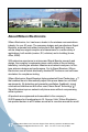
3301 East Deseret Drive, St. George, UT 84790
For additional Technical Support visit www.WilsonElectronics.com
or email at: tech@wilsonelectronics.com
Phone: 866-294-1660 Local: 435-673-5021 Fax: 435-656-2432
www.twitter.com/WilsonCellular www.facebook.com/WilsonCellular