Pioneering for You Wilo-Helix V, FIRST V, 2.0-VE 2-4-6-10-16 en Installation and operating instructions 4143727 ·• Ed.
Fig.
Fig.
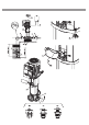
Fig. 3 Fig. 4 E A D Type AJ AG F AK C B H Type AH F E A D AG AK C B AJ Helix V(F), 2.0-VE 2... Helix V(F), 2.0-VE 4… Helix V(F), 2.0-VE 6… Helix V(F), 2.0-VE 10… Helix V(F), 2.0-VE 16… Helix V(F), 2.0-VE 2… Helix V(F), 2.0-VE 4… Helix V(F), 2.0-VE 6… Helix V(F), 2.0-VE 10… Helix V(F), 2.
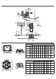
Fig. 5 Fig. 6 MOT. 230-400V (220-380V/240-415V) W2 U2 U1 V1 ≤4 KW HIGH L1 L2 L3 VOLTAGE < 3x400V (3x380V/3x415V) V2 W1 3x230V (3x220V/3x240V) LOW VOLTAGE L1 L2 L3 < ܾ L1 L2 L3 MOT. 400V (380V∆/415V∆) >4 KW 3x400V (3x380V/3x415V) 3x400V (3x380V/3x415V) Fig.
English ...............................................................................................................
en Sommaire 1 General....................................................................................................................................................................................... 9 1.1 About this document ........................................................................................................................................................................................ 9 2 Safety ..................................................................................
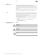
General 1 1.1 General About this document en The language of the original operating instructions is English. All other languages of these instructions are translations of the original operating instructions. These installation and operating instructions are an integral part of the product. They must be kept readily available at the place where the product is installed. Strict adherence to these instructions is a precondition for the proper use and correct operation of the product.
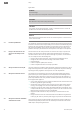
en Safety Signal words DANGER Imminent danger. May result in death or severe injuries if the hazard is not prevented. WARNING Non-observance may result in (very) severe injury. CAUTION The product risks becoming damaged. “Caution” is used when there is a risk to the product if the user does not observe procedures. NOTICE Note containing useful information for the user about the product. It assists the user in the case of an issue; 2.
Transport and interim storage en Work on the product/unit must only be carried out when at a standstill. It is mandatory that the procedure described in the installation and operating instructions for shutting down the product/unit be complied with. Immediately on conclusion of the work, all safety and protective devices must be put back in position and/or recommissioned. 2.
en 5 5.1 Technical data Technical data Type key Example: Helix V1605 or Helix2.0-VE1602-1/16/E/KS/400-50xxxx Helix V(F) Vertical high-pressure multistage centrifugal pump in in-line design Helix FIRST V(F) (F) = VdS certified pump version Helix2.0-VE With frequency converter 05 Number of impellers 1 Pump material code 16 Nominal volume flow in m³/h 1 = Pump housing stainless steel 1.4301 (AISI 304) + hydraulics 1.4307 (AISI 304) 2 = Pump housing stainless steel 1.
en Technical data Frequency See pump rating plate Electrical voltage Capacitor value (μF) in single-phase version Other data Humidity < 90% without condensation Altitude < 1000 m (> 1000m on request) Maximum suction head According to pump’s NPSH Sound pressure level dB(A) 0/+3 dB(A) Power (kW) 0.37 0.55 0.75 50H z 60H z 5.3 1.1 1.5 2.2 3 4 5.5 7.5 11 15 18.
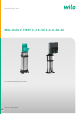
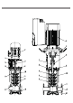
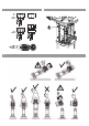
en 6 6.1 Description and function Description and function Product description Fig. 1 1. Motor connection bolt 2. Coupling gard 3. Mechanical seal 4. Hydraulic stage casing 5. Impeller 6. Pump shaft 7. Motor 8. Coupling 9. Lantern 10. Liner 11. Flange 12. Pump housing 13. Base plate Fig. 2, 3 1. Strainer 2. Pump suction valve 3. Pump discharge valve 4. Check valve 5. Drain + priming plug 6. Air bleed screw + Filling plug 7. Tank 8. Foundation block 9. Grease 10.
Installation and electrical connection 7.2 Installation en The pump must be installed in a dry, well-ventilated and frost-free place. CAUTION Possible damage of the pump! Dirt and solder drops in to the pump body can effect the pump operation. • It is recommended that any welding and soldering work be done before installing the pump. • Thoroughly flush the system out before installing the pump. ƒ The pump must be installed in an easily accessible position to facilitate inspection or replacement.
en Installation and electrical connection WARNING Risk of fall! The pump must be never carried by using motor hooks: these are only designed to lift the motor alone. 7.3 Pipe connection ƒ Connect the pump to the pipes by using appropriate counterflanges, bolts, nuts and gaskets. CAUTION Tightening of screws or bolts must not exceed. Configuration PN16 / PN25 M10 – 20 N.m - M12 – 30 N.m Configuration PN40 M12 – 50 N.m - M16 – 80 N.m Use of impact wrench is prohibited.
Commissioning 7.5 en Electrical connection WARNING Electrical shock hazard! Dangers caused by electrical energy must be excluded. • Electrical work by a qualified electrician only! • All electrical connections must be performed after the electrical supply has been switched off and secured against unauthorized switching. • For safe installation and operation a proper grounding of the pump to the power supply’s grounding terminals is required.
en Commissioning WARNING Risk of scalding! When the pumped liquid is hot and the pressure high, the stream escaping at the venting screw may cause burns or other injuries. ƒ Open the guard valve on the suction side completely (2). ƒ Start the pump and check if direction of rotation matches the one printed on pump plating. If this is not the case, interchange two phases in the terminal box.
Maintenance en WARNING important noise Noise emitted by most powerful pumps could be very high : protection must be used in case of long stay close to the pump. CAUTION Possible damage of the pump Installation must be designed in order that no one could be hurt in case of fluid leakage (mechanical seal failure …). 9 Maintenance All servicing should be performed by an authorized service representative! DANGER Electrical shock hazard! Dangers caused by electrical energy must be excluded.
en 10 Faults, causes and remedies Faults, causes and remedies DANGER Electrical shock hazard! Dangers caused by electrical energy must be excluded. All electrical work must be performed after the electrical supply has been switched off and secured against unauthorized switching. WARNING Risk of scalding! At high water temperatures and system pressure close isolating valves before and after the pump. First, allow pump to cool down.
Disposal en NOTICE Disposal as domestic waste is forbidden! In the European Union, this symbol can appear on the product, the packaging or the accompanying documentation. It means that the electrical and electronic products in question must not be disposed of along with domestic waste. To ensure proper handling, recycling and disposal of the used products in question, please note the following points: ƒ Only hand over these products at designated, certified collecting points.
Local contact at www.wilo.com/contact Pioneering for You WILO SE Wilopark 1 44263 Dortmund Germany T +49 (0)231 4102-0 F +49 (0)231 4102-7363 wilo@wilo.com www.wilo.