
Install Instructions

8 50-13-002-0415
7 Installation and electrical connection
Installation and electrical work in compliance with any local codes
and by qualied personnel only!
WARNING! Bodily injury
Existing regulations for the prevention of accidents
must be observed.
WARNING! Electrical shock hazard
Dangers caused by electrical energy must be
excluded. National Electrical Codes, local codes and
regulations must be followed.
7.1 Installation
• The pump must be installed in a dry, well-ventilated and frost-
free place.
CAUTION! Possible damage of the pump
Dirt and solder drops in to the pump body can effect
the pump operation.
• It is recommended that any welding and soldering
work be done before installing the pump.
• Thoroughly ush the system out before installing
the pump.
• The pump must be installed in an easily accessible position to
facilitate inspection or replacement.
WARNING! Risk of accident by hot surfaces
The pump must be positioned so that someone
cannot come into contact with the hot pump
surfaces while operation. The pump surface has a
class F temperature rise.
• It is recommended that isolation valves be installed on the suction
and discharge side of the pump. This will save having to drain and
rell the system if the pump needs replacing. The valves are to
be installed so that any water that escapes cannot drip onto the
pump motor or terminal box.
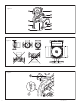
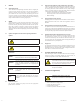
• Pump must be installed with the shaft in the horizontal position
in such a way that it is not stressed by the pipework. (Installation
positions in Fig. 2)
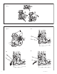
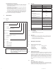
• An arrow on the pump housing indicates the direction of water
ow (Fig. 3, pos. 1).
• In order to obtain the correct terminal box position the motor
housing can be turned after removing the two allen screws (Fig.
4).
• Permitted terminal box positions see Fig. 2
CAUTION! Possible damage of the pump
Do not damage the at gasket between pump head
and pump housing. Check the correct position. If
necessary use a new gasket: Ø 86 x Ø 76 x 2.0 mm EP.
• Replace the pump head onto the pump housing and tighten the
allen screws evenly.
• After replacing, check that the rotor shaft still rotates freely.
Remove the plug (located in the middle of the nameplate), insert
a at head screwdriver into the slot end of the shaft and turn to
ensure free rotation.
• Between the stator housing and pump volute, there are four drain
holes to allow condensed water to escape (Fig. 3, pos. 2).
CAUTION! Possible damage of the pump!
The motor and condensate holes must remain free.
For units which are to be insulated, only the pump
volute may be insulated.
7.2 Electrical connection
WARNING! Electrical shock hazard
Dangers caused by electrical energy must be
excluded.
• Electrical work by a qualied electrician only!
• National Electrical Codes, local codes and
regulations must be strictly followed.
• All electrical connections must be performed
after the electrical supply has been switched off
and secured against unauthorized switching.
• For safe installation and operation a proper
grounding of the pump to the power supply’s
grounding terminals is required.
• The operating voltage and frequency are marked on the
nameplate.
• The pump must be connected to the power supply by a solid
cable equipped with a grounded plug-connection or a main
power switch.
• The motor is impedance protected so motor overload protection
is not required.
• A minimum cable size of 14 AWG should be used (refer to the
local codes).
NOTE!
When using the pump in systems with water
temperature exceeding 194°F (90 °C), a connecting
cable with corresponding heat resistance must be
used.
• The supply cable must be laid so that it never touches the
pipework and/or the pump and motor casing.
• The connecting cable can be fed through the cable entry either
above or below the terminal box. The cable entry which is not
used must be closed by a blind plug.
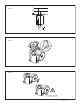
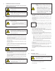
• Connect power as shown in g. 5 and g. 6
• Loosen the terminal box screw and remove the screw and cover.
• The terminal box is equipped with Quick-action snap-lock
terminal connection. Instructions:
Fig. 5 A: Push down the snap-lock lever towards the horizontal
position until the resistance becomes greater (with very little
force)
Fig. 5 B: Take the cable to be connected, push down the snap-
lock lever to a fully horizontal position and insert the cable. To
x the cable end release the lever.
Fig. 5 C: Turn back the lever to its original vertical position.
• Feed the appropriate size cable to the hole in the side of the
terminal box.
• Connect the leads of the cable according to the L and N cable
entry respectively and the ground lead to the cable entry.
• Replace the terminal box cover.
• The pump/installation should be grounded in compliance with
local regulations. A ground fault interrupter can be used as extra
protection.
8 Start up
8.1 System lling - Venting
• Proper ll and pressurize the system with liquid.
CAUTION! Possible damage of the pump
Never operate the pump dry. The system must
be lled before starting the pump. Ensure that all
isolation valves are open.
• The pump is normally vented automatically after a short
operational period. If it becomes necessary to vent the pump,
please observe the following procedure:
• Switch off pump.