
Install Instructions


7 50-13-002-0415
Permissible liquids and requirements:
• Domestic hot water. In open domestic hot water systems the
pumps should be in bronze body and in accordance with all other
specic drinking water laws.
• Heating water acc. the requirements of accepted standards of
water quality in heating systems.
• Water and water/glycol mixtures in a maximum ratio up to 1:1.
Glycol mixtures require a reassessment of pump hydraulic data in
line with the increased viscosity and depending on mixing ratios.
Only approved makes of additives with corrosion inhibitors must
be used in strict compliance with manufacturers’ instructions.
For use of other kinds of liquids consult WILO rst.
5 Technical data
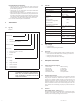
5.1 Type Key
Example:
Star S 16 () FX
Circulator pump
S = 3-Speed
= constant speed (no letter)
Maximum head [ft]
Pump housing
= Cast iron (no letter = cast iron)
Z = Stainless steel
B = Bronze
Pipe connection
F = Flange
FX = Flange rotated 90°
U = Union connection
S5 = ½ Internal sweat
S7 = ¾ Internal sweat
NOTE! These pumps have a class F temperature rise and
are intended for connections to metal connectors.
When using non-metallic distribution devices,
proper consideration is needed to care for the
safety of the installation.
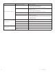
5.2 Data table
Voltage 1~115 V
Mains frequency 60 Hz
Power consumption See name plate
Speed setting 3-speed
(Star S… only)
Fitting length: Inch (mm)
Flange F 6
3
/
8
(162)
Union connection
(1-speed Bronze casing ONLY)
6 (152.4)
Sweat connection
(1-speed Bronze casing ONLY)
5 (127)
Liquid temperatures 14°F (-10°C) up to 230°F
(110°C)
Domestic hot water temperature < 150°F (66°C)
Max. Ambient temperature 104°F (40°C)
Max. working pressure 145 psi
Min. inlet pressure at suction side at 122°F
(50°C)
203°F
(95°C)
230°F
(110°C)
0.7 psi 4.4 psi 14.5 psi
Motor Temperature Rise Class F (311°)F
5.3 Scope of Supply
• Complete pump
• Installation and operating instructions
5.4 Accessories
Accessories such as companion anges must be ordered separately
• Unions (sweat and threaded) for the screwed-pipe connection.
• Flanges for ange-pipe connection.
• Closing caps for terminal box cable entry
6 Description and function
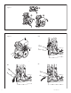
6.1 Product description (see Figure 1)
1. Terminal box
2. Suction side
3. Pump housing
4. Discharge side
5. Condensate outlet
6. Motor housing
7. Cable entry
8. Venting plug
9. Name plate
10 3-speed switch
6.2 Design of pump and motor
In the wet-rotor pump all rotating parts are surrounded by the liquid
being pumped. A shaft seal, which would be subject to wear is not
required. The pumping medium lubricates the bearings and cools
both bearing and rotor. The pump is maintenance free. The motor is
impedance protected so motor overload protection is not required.
Even the maximum overload current cannot damage the motor. The
motor operates non-overloading. The pump is protected in all three
speeds.
6.3 Functions
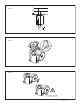
Speed setting of Star S… pumps (Figure 7)
The speed of the pump can be adjusted with a 3-speed rotary switch.
In position 1 the speed is approx. 40...50 % of the maximum speed
with the power consumption being reduced to 50 %.