Pioneering for You Consulting guide Wilo-Stratos MAXO
NOW. PUMP TECHNOLOGY OF THE FUTURE WILO-STRATOS MAXO: THE WORLD’S FIRST SMART PUMP*. NEW Your new partner is the most flexible pump: the Wilo-Stratos MAXO is the perfect fit for any application and ensures optimal system efficiency thanks to its intelligent control mode. Furthermore, the pump can be integrated into all relevant systems due to diverse interfaces. And with optimised and innovative energy-saving features the Wilo-Stratos MAXO meets the changing requirements superbly.
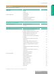
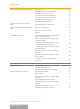
Planungshinweise Applications and fields of application Introduction Applications Fields of application 5 Heating 5 Drinking water 5 Viscous fluids 6 Installation environment 6 Cooling 5 Permitted fluids 5 Permitted operating temperatures 6 System pressure (rated pressure) 6 Minimum inlet pressure 7 Application-based control mode setting 7 Heating: Radiator consumer circuit 8 Heating: Ceiling heating consumer circuit 9 Dimensioning of the Stratos MAXO Hydraulic dimensioning Flow
Consulting guide Additional functions for the control modes No-Flow Stop 18 Nominal duty point in Δp-v control 19 Automatic detection of setback operation Q-Limit Min (minimum volume flow limit) Q-Limit Max (maximum volume flow limit) Switching between heating/cooling Detection of thermal disinfection 19 19 19 20 20 Data collection functions of the Stratos MAXO Heating/cooling quantity measurement 20 Pump functions independent of the control mode Double pump management 21 Automatic venting
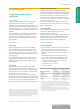
1 Consulting guide 2 Applications and fields of application 2.1 Introduction The Stratos MAXO series is a high efficiency glandless pump and the world’s first smart-pump*. With its optimised and innovative energy-saving functions, it sets new energy efficiency standards for heating, cooling and drinking water applications. Furthermore, the outstanding user-friendliness offers a hitherto unparalleled ease of operation.
Consulting guide ƒƒ The Stratos MAXO is resistant to water-glycol mixtures for cooling applications or for use in geothermal circuits. These water-glycol mixtures are produced by different manufacturers; the mixtures’ characteristics, substances and concentrations vary slightly and must be used in accordance with the manufacturers’ recommendations. ƒƒ Various fluids can be used for the application of e.g. heat pumps in geothermal circuits.
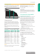
'HOLYHU\ KHDG + >P@ Area III (right-hand third) The controlled pump will only operate in the least efficient operating area at its design point (on the warmest/coldest day of the year), i.e. for 2 % of its operating time. , In case of higher fluid temperatures, fluids of lower density, higher flow resistances or lower atmospheric pressure, adjust the values accordingly. The maximum installation height is 2000 metres above mean sea level (MSL). 3.1.
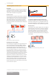
Consulting guide 4.1.2 Heating: Radiator consumer circuit Description The pump is installed in a consumer circuit that supplies a static heating system with radiators. The Δp-v, Dynamic Adapt plus or T-const constant hall temperature control modes could be selected for this application. Pressure control If the heating circuit supplies multiple rooms, the radiators will be fitted with control valves to regulate the individual rooms’ temperatures.
Hall temperature control If the heating circuit supplies heat to a large thermal zone, e.g. a hall, the control valves on the underfloor heating’s distributor connections are redundant and are often not present in existing buildings. The pump can then directly control the temperature to reach the desired setpoint using the T-const constant hall temperature control mode.
Consulting guide 4.1.5 Heating: Fan heater consumer circuit The pump is installed in a consumer circuit that supplies very fast air heating, e.g. a fan heater. The Δp-v, Dynamic Adapt plus or T-const constant hall temperature control modes could be selected for this application. Pressure control If the heating circuit supplies multiple rooms, the radiators will be fitted with control valves to regulate the individual rooms’ temperatures.
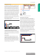
Heating, air conditioning, cooling Consulting guide ¨7 Temperature control ΔT-const of inputs via a heat exchanger Heating: Temperature control T-const behind the heat exchanger Temperature control: ΔT-const between primary side feed and secondary side feed The temperature difference between the heat exchanger’s primary and secondary feeds is controlled to reach the defined setpoint. The volume flow in the primary circuit is thereby aligned with the secondary volume flow.
Consulting guide Temperature control: Constant secondary feed temperature T-const The feed temperature behind the hydraulic shunt (secondary side) is regulated to the defined setpoint by adjusting the speed of the pump in front of the shunt. It is also necessary to install a temperature sensor (PT1000 or active sensor with 0…10 V and 4…20 mA output) in the secondary feed. The pump is connected via one of the two analogue inputs.
4.1.8 Cooling: Ceiling cooling consumer circuit The pump is installed in a consumer circuit that supplies fast surface cooling, e.g. a cooling ceiling or ceiling canopy. The control modes Δp-c, Dynamic Adapt plus or T-const constant hall temperature can be used for this application. Pressure control If the cooling circuit supplies multiple rooms, the cooling area circuits will be fitted with control valves to regulate the individual rooms’ temperatures.
Consulting guide Hall temperature control modes If the cooling circuit cools a large thermal zone, e.g. a hall, the control valves on the ceiling cooling’s distributor connections are redundant and are often not present in existing buildings. The pump can then directly regulate the hall temperature to the desired setpoint using the T-const constant hall temperature control mode.
4.1.10 Cooling: Air-conditioning device consumer circuit The pump is installed in a consumer circuit that supplies very fast air cooling, e.g. an air-conditioning device. The control modes Δp-v, Dynamic Adapt plus or T-const constant hall temperature can be used for this application. Pressure control If the cooling circuit supplies multiple rooms, the airconditioning device will be fitted with control valves to regulate the individual rooms’ temperatures.
Consulting guide 4.2 Basic control modes In addition to the option of selecting the control mode based on the application, the basic control modes can also be directly adjusted. This is the case, for example, when the required settings for the field of application are already known (e.g. in the case of pump replacement) or if none of the pump’s predefined applications are suitable for the specific installation.
Control properties: The pump variably adjusts the required volume flow according to the opened and closed valves on the consumers, thereby adjusting the power required. It saves electrical pumping energy in comparison to Δp-c. The setpoint is defined using the duty point, which can usually be taken from the pipe network calculation. 'HOLYHU\ KHDG + >P@ Fields of application e.g.
Consulting guide 4.2.7 Volume flow Q-const In the Q-const constant volume flow control mode, the pump keeps constant at the specified volume flow setpoint. For this purpose, the speed increases within the permitted range if the measured volume flow is less than the setpoint, and vice versa. Control properties: The desired volume flow is kept constant, independent of the differential pressure. Fields of application e.g.
4.3.2 Automatic detection of setback operation The pump detects a significant reduction in fluid temperature over a defined period of time. The pump thereby deduces that the heat generator is in setback operation. The pump independently reduces its speed until a high fluid temperature is once again detected over a longer period of time. This leads to savings in electrical pumping energy. Benefit: Electrical pumping energy is saved by avoiding unnecessary running times. Field of application e.g.
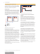
Consulting guide 4.3.6 Switching between heating/cooling If the Stratos MAXO is installed in a circuit used for both heating and cooling, the pump can switch between heating or cooling depending on the current application. This is achieved by an external binary contact, through a building automation data item or by detecting the feed temperature. If the feed temperature is over e.g. 25 °C, the pump enters heating mode with the corresponding control mode setting (e.g. Dynamic Adapt plus).
4.5 Pump functions independent of the control mode 4.5.1 Double pump management The Stratos MAXO can be operated either with two single pumps or as a double pump variant with double pump management. The double pump variant is fully wired-up upon delivery and is configured as a double pump. Only one of the two pump modules has a fully functional LCD colour display. The second pump module is equipped with a 7-segment LED display.
Consulting guide 4.6.4 PT 1000 B pipe surface contact sensor to detect thermal disinfection When used for domestic hot water circulation, the Stratos MAXO-Z can detect when heating starts in the hot water tank for thermal disinfection purposes. To achieve this, a temperature sensor must be attached to the pipe at the tank’s hot water outlet. An immersion temperature sensor is not necessary.
4.6.6 Differential pressure sensor for the Δp-c index circuit evaluator A differential pressure sensor is connected to the Stratos MAXO in order to facilitate the Δp-c index circuit evaluator. The distance between Stratos MAXO and the least hydraulically favourable location in the pipe network, where the desired differential pressure should be maintained, is usually considerable. Differential pressure sensors with the 4 – 20 mA signal are therefore recommended.
Consulting guide CIF module types Line type BACnet CANopen LON Modbus RTU PLR Bus cable, twisted in pairs, braided shield, 120 Ω characteristic impedance CAN bus cable, twisted in pairs, shielded, 1 x 2 x 0.5 mm² / 120 Ω characteristic impedance (line type B in accordance with TIA 485-A) Twisted in pairs, shielded Bus cable, twisted in pairs, braided shield, 120 Ω characteristic impedance Twisted in pairs, shielded 1000 m 200 m Line length 1000 m 200 m 900 m (bus topo logy with max.
80 Ø 185 Ø 145 Ø 130 Ø 118 DN 65 4 x Ø14 80 4 x Ø19 Example combination flange PN 6/10 for DN 65 In nominal sizes DN 80 and DN 100, the flange standard versions PN 6 and PN 10 are available. Special versions of pumps DN 32 to DN 100 are also available in PN 16. Detailed specifications can be found under the Stratos MAXO series in the catalogue.
Consulting guide 5.1.2 Permitted installation positions The Stratos MAXO can be installed in the positions listed below. Impermissible positions are also shown. 5.1.3 Installation dimensions of the Stratos MAXO The pump dimensions must be considered when installing the Stratos MAXO with distributors and in piping systems, so that the clearances around distribution outlets and with surrounding components are taken into account. The dimensions of all Stratos MAXO variants are detailed in the catalogue.
5.2.2 Motor protection The standard integrated motor protection device reliably protects the pump, in all settings, against excess temperature, excess current and blocking. This has the following advantage: ƒƒ No external motor protection switch is required. The connection instructions of the local energy supply companies must be observed.
Consulting guide 5.2.6 Connection of Wilo Net BUS system Wilo Net is a stand-alone BUS system which enables up to 11 Stratos MAXO pumps to communicate with one another. Wilo Net is used e.g. in the Multi-Flow Adaptation control mode, in which the feeder pump is informed of the respective volume flow demands of the connected pumps and thereby supplies the total required volume flow. The 3-wire 3 x 1.5 cable is connected to the Wilo Net connection with ferrules.
WILO SE Nortkirchenstraße 100 D-44263 Dortmund Germany SE 41 02-0 TWILO +49 231 100 FNortkirchenstraße +49 231 41 02-7363 44263 Dortmund wilo@wilo.com Germany www.wilo.com T +49 231 4102-0 F +49 231 4102-7363 wilo@wilo.com www.wilo.