
User Guide

English
32 Subject to technical alterations! WILO SE 03/2016
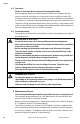
8.4 Setting the pump power
During the planning phase the system is designed for a certain duty point
(hydraulic peak load point for calculated maximum heating requirement). The
pump performance (delivery head) is set during commissioning according to the
duty point of the system (see also 4.3). The factory setting does not correspond
to the pump performance required for the system. It is determined by means of
the curve diagram for the selected pump type (from catalogue/data sheet). See
also figs. 7 to 9.
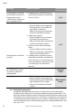
Drinking water circulation
systems with resistance in
the generator circuit
≤ 50% of the resistance in
the ascending section
5. Drinking water circulation systems
with thermostatically controlled line
shut-off valves
Δp-c
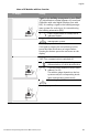
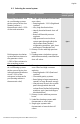
Heating systems 1. Two-pipe systems
• Pump installed in the supply pipe.
• Flow temperature controlled by
atmospheric conditions.
With increasing flow temperature
the flow rate will be increased.
2. Single-pipe systems
• Pump installed in the return pipe.
• Constant flow temperature.
With increased return temperature
the flow rate will be lowered.
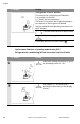
3. Primary circuits with condensing
boiler
• Pump installed in the return pipe.
With increased return temperature
the flow rate will be lowered.
Δp-T
Drinking water circulation
systems
4. Drinking water circulation systems
with thermostatically controlled line
shut-off valves or constant flow rate.
If the temperature is increased in the
circulation pipe, the flow rate is
reduced.
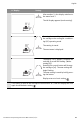
Heating-/ventilation- and
air conditioning systems
Circulation systems for
drinking water
1. Constant flow rate
Regulator
mode
Heating systems 1. All systems
• Pump installed in the supply pipe.
• Flow temperature will be lowered in
light loads periods (i.e. night).
• Pump runs 24h without external
control.
Night setback
mode
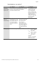
Unit type System conditions Recommended
control system