Wilo-Stratos /-D/-Z Installation and operating instructions Notice de montage et de mise en service 2 095 796-Ed.
Fig. 1a: Fig. 1b: 2 1 1.1 Fig. 2a: Fig. 3: 1.2 1.3 Fig.
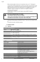
Fig. 4: Fig. 5: ! Achtung Attention 1 - 230V 230V~ FC Achtung Option Netzspannung IF-Modul Attention Mains Voltage Fig. 6: Fig. 7: H HH H max H max 1 1 H Hss 1 1 H Hss 2 Hs 2 Hs 2 ½Hs Hmin 2 Hmin Q Q Q Fig. 8: Hs Hs Hs max Hs var.
Fig. 9: Fig.
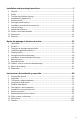
Installation and operating instructions ..................................................................3 1 2 3 4 5 6 7 8 9 10 11 12 General ................................................................................................................................... 3 Safety ..................................................................................................................................... 3 Transport and interim storage .............................................................
2
English 1 General About this document These Installation and Operating Instructions form an integral part of the product. They must be kept close to the product and in readiness whenever required. Precise observance of these instructions is a pre-condition for use of the product for the intended purpose and for its correct operation. These Installation and Operating Instructions conform to the relevant version of the equipment and the underlying safety standards valid at the time of going to press.
English Signal words: DANGER! Imminently hazardous situation. Will result in death or serious injury if not avoided. WARNING! The user can be exposed to (severe) injury. 'Warning' refers that harm to the user when the user is neglecting the procedure. CAUTION! The product is at risk of damage. 'Caution' refers to the product when the user is neglecting the procedures. NOTE: A notice with useful information for the user in relation to the product. It attends the user to possible problems. 2.
English 2.6 Unauthorized alterations and manufacture of spare parts Alterations to the pump or installation may only be carried out with the manufacturer's consent. The use of original spare parts and accessories authorized by the manufacturer will ensure safety. The use of any other parts may invalidate claims involving the liability of the manufacturer for any consequences. 2.
English • Water and water/glycol mixtures in a maximum ratio up to 1:1. High glycol concentration and low temperature systems may require a reassessment of the hydraulic data to compensate for the increased viscosity (please contact your WILO representatives for more information). Use of additives (corrosion inhibitors, oxygen scavengers etc.) must be in compliance with the manufacturer instructions. • If other fluids or additives are used, please contact WILO for proper authorization.
English Min. pump inlet pressure [psi] at the suction side during operation by WiloStratos model: At these liquid temps TMed 1.25 inch 1.5 and 2 inch 3 inch 14°F...122°F (- 10°C...+50°C) 203°F (+95°C) 230°F (+110°C) 4.4 (psi) 7.3 (psi) 10.2 (psi) 14.5 (psi) 17.4 (psi) 21.8 (psi) 23.2 (psi) 26.1 (psi) 33.4 (psi) The values apply up to 984 ft above sea level, add-on for higher altitudes: 0.15 psi/328 ft increase in height 5.
English The main benefits of electronic control are: • it saves energy while reducing operating costs, • it reduces noise caused by the excess flow, • it does not require pressure bypass valves. This wet rotor pump is designed to have all rotating parts surrounded by the liquid being pumped. The pump is maintenance free and requires no further maintenance after the air bleeding procedure during the initial start-up (no after start-up maintenance).
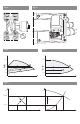
English 6.2.2 Differential-pressure control systems The control systems which can be selected are: • 'p-v: (Factory default setting) The electronics increase the pump's differential pressure set point in a straight line between ½ Hs and Hs. The differential pressure set point Hs increases or decreases in accordance with the required flow rate (fig. 6).
English • Pump kick: Any pumps switched off via the menu (ON/OFF), a bus communication, the infrared interface, the Ext.Off control input or 0-10V start running for a short time every 24 hours to prevent blockages in the event of long periods of standstill. The mains voltage must not be interrupted for this function. If the mains is intended to be switched off for a long period of time, the pump kick must be assumed by the heating/boiler control system by briefly switching on the mains voltage.
English • In the event of a break in communication: The slave pump runs at the last set value of the master prior to the interruption. • Pump swap: If only one pump is operational (duty/standby, peak- or low-load operation), the pumps are swapped after every 24 hrs’ of actual operating time. Both pumps are running at the time of the pump alteration in order to ensure that operation is not interrupted.
English Symbol Definition Manual control mode deactivates the module pressure variations. The speed of the pump is kept at a constant level. The speed is set internally using the contol button (fig. 9). Pump set to a constant speed (2.600 rpm example shown) - manual control mode. In the manual control mode, the speed or nominal lift of operating mode 'p-c or 'p-v of the pump is set via input 0...10 V of the Stratos IF module Ext.Min. The button then has no set value input function. (fig.
English Menu structure: There are three menu levels. The levels beneath the display of the basic settings are always accessed from 1 level by pressing the control button for different lengths of time.
English • The pump must be installed in an easily accessible position to facilitate inspection or replacement. • The pump should never be located at the lowest point of the piping system, where dirt and sediment collect. Nor should it be located at the highest point of the piping system, where air accumulates. Please ensure at least a minimum of three pipe diameters of straight on the suction side of the pump.
English DANGER! Electrical shock hazard! If the pump is operated by means of a generator, a dangerous voltage is created at the motor terminals after the control module is removed. The motor terminals are designed as VDE-approved bushings, so that there is no danger if simply touched with the finger. However, there would be a danger if a pointed object (nail, screwdriver, wire) were poked into one of the bushings. 7.1.
English 7.2 Electrical connection • • • • DANGER! Electrical shock hazard! Dangers caused by electrical energy must be excluded. Electrical work by a qualified electrician only! National Electrical Codes, local codes and regulations must be strictly followed. All electrical connections must be performed after the electrical supply has been switched off and secured against unauthorized switching.
English 7.2.1 Electrical pump connection (fig. 5) • 230 V~, : Mains voltage, single-phase current 1~230 V AC ±10%, 60 Hz Voltage across terminals “230V~” must be total 230 volt either • 230 volt “hot” lines and neutral line or • two 230 volt “hot” lines. • FC: A built-in collective fault signal is available on the FC (fault contact) terminals as a potential-free closed contact. Permissible contact load: • minimum: 12 V DC, 10 mA, • maximum: 250 V AC, 1 A. Max.
English 8 Commissioning 8.1 Filling and Venting • Proper fill and pressurize the system with liquid. CAUTION! Possible damage of the pump! Never operate the pump dry. The system must be filled before starting the pump. Ensure that all isolation valves are open. • The pump is normally vented automatically after a short operational period. WARNING! Risk of burning! Depending on the operating condition of the pump and/or installation (fluid temperature) the entire pump can become very hot.
English Switchover of the display Horizontal Vertikal Position setting in menu point 3 8.2.3 Settings in the menu The following menus appear in succession on the pump display: (horizontal representation of display) Single pump mode: Setting when first used / Menu order during standard use LC display Setting After switching on the module, all symbols appear on the display for 2 seconds. The current setting then engages.
English LC display Setting Current (basic) setting (factory default): auto • automatic night setback enabled, Pump runs in control mode • missing = Single-head pump e.g. H 18.0 ft • present differential pressure setpoint HS = 18.0 ft at same time ½ Hs max (factory setting depending on pump type) • Control mode 'p-v The differential pressure set point can be altered by turning the control button. The new differential pressure set point flashes. The new setting is stored by pressing the button briefly.
English LC display Setting The currently set control mode flashes. By turning the contro button other control modes can be selected. The new selected control mode flashes. Pressing the button stores the new control mode and switches to the next menu. Menu point only appears if a Stratos IF module was inserted with input 0...10 V. Switch input 0...10 V on/off Activate input 0...10 V: “ON” and the “module motor symbol” appears in the display. The setting can be altered by turning the control button.
English LC display Setting Switch pump on/off. Switch on pump, "ON" and the “module motor symbol” appear in the display The setting can be altered by turning the control button. Switch off pump, "OFF" appears in the display and the “motor symbol” disappears. Setting stored. Menu point selected Either flash is skipped if regulator mode was auto • automatic night setback Pump runs in standard mode Menu point then shows "auto " during autom.
English LC display Setting In single-pump mode the display returns to basic setting . In the event of an error the error menu appears before the basic setting . In double pump mode (twin-head pump or two single pumps) the display jumps to menu . Double pump mode (as twin-head pump or two single pumps): Setting when starting up for the first time (vertical display) LC display Setting When the module is switched on all symbols appear in the display for 2 seconds. Menu then appears.
English Double pump mode: Menu order during normal use: After switching on the module, all symbols appear on the display for 2 seconds. The current setting then sets itself. When "scrolling" in the MA display the same menu order ... appears as for the single pump. Then the MA menu appears and remains on the screen permanently. LC display Setting SL appears on this display by on MA. The other (right-hand) pump becomes the master if SL is confirmed by . Master and slave have now been exchanged.
English Options menu: Selection of operating mode Heating (HV) / Refrigeration Air-conditioning (AC) and conversion from US to SI units LC display Setting In the basic settings (menu level 1), press the operating button for > 6 s. After approx. 1 s, the menu level 2 appears (position setting of the display screen). After another 5 s, the display switches to the menu level 3 The HV display appears (works setting).
English The display “m ft” appears, for which the unit that is set will be flashing. (Works setting [ft]). Rotating the control button will change the setting to [m]. The new setting will begin flashing. The new setting is saved by briefly pressing the button. Display returns to basic setting . If no setting is made in the subsequent menu within 30 s, then the display will once again show the basic setting .
English 8.3 Selecting the control system Unit type System conditions Heating-/ventilation- and air conditioning systems with a system friction loss (heating radiator + thermostatic valve) d 25% of the total resistance 1. Two-pipe systems with thermostatic/ zone valves • Flow head > 13.
English Unit type System conditions Heating systems 1. Two-pipe systems • Pump installed in the supply pipe. • Flow temperature controlled by atmospheric conditions. With increasing flow temperature the flow rate will be increased. 2. Single-pipe systems • Pump installed in the return pipe. • Constant flow temperature. With increased return temperature the flow rate will be lowered. 3. Primary circuits with condensing boiler • Pump installed in the return pipe.
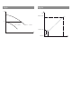
English Control modes 'p-c, 'p-v and 'p-T: 'p-c (fig. 7) Operating point on max. speed curve Operating point in control range Setting range 'p-v (fig. 6) Draw a line from the operating point to the left. Read set value Hs and set the pump in accordance with this value. Draw a line from the Continue the standard operating point to the line until it meets the left. Read set point Hs max. speed curve, and set the pump in then continue accordance with this horizontally to the value.
English 10 Faults, causes and remedies Refer to the “Fault signal / warning message” sequence display and Tables 10, 10.1, 10.2 when handling faults. Faults Causes Remedy Pump is not running although the current entry is switched on. Electric fuse defective. Check the fuses. Pump has no voltage. Resolve the voltage interruption. Increase the system admission pressure within the admissible range. Check the delivery head and set it to a lower height if necessary. Pump is making noises.
English Code Symbol No. flashing Problem cause remedies E04 Supply terminal Supply terminal Mains undervoltage Mains overloaded Mains overvoltage E10 Motor Pump blocked Faulty supply by the electricity supply company e.g.
English Code Symbol No.
English Process presentation Fault/warning signal in HV operation Error messages: Warning messages: Error PUMP shuts down Waiting time 5 min Autostart PUMP switches on See table Code no. Error LED “on“ DP: switch to other pump No manual reset possible Operating relay SBM opens for Stratos IF module SBM and Ext.Off/SBM E03 E04 E05 E07 E09 E11 E38 E50 E51 E52 E53 E54 MA Pump shuts down while error present E04 E05 Control mode Longer than 5 min No. of errors in 24 hrs No.
English Process presentation Fault/warning signal in AC operation Error messages: Warning messages: Error E04 E05 E10 E20 E21 Error E23 E25 E30 E31 E36 See table PUMP shuts down Exception: E10 Deblocking routine starts. (max. 3 times or max. 40 s) Pump switches of, if the blockage is not eliminated. Manual reset PUMP switches on E03 E07 E09 E11 E38 E50 E51 E52 E53 E54 MA Code no.