
User Guide

English
Installation and operating instructions Wilo-Stratos GIGA 47
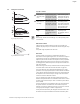
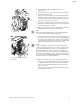
9.4 Setting the control mode
Δp-c/Δp-v control:
NOTE:
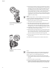
Alternatively, manual control mode (Fig. 44) or PID operating mode
can also be set.
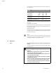
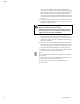
Manual control mode:
“Manual control” mode deactivates all other control modes. The
speed of the pump is kept to a constant value and set using the rotary
knob.
The speed range is dependent on the motor.
PID control:
The PID controller in the pump is a standard PID controller, as
described in control engineering literature. The controller compares a
measured process value to a predefined setpoint and attempts to
adjust the process value to match the setpoint as closely as possible.
Provided appropriate sensors are used, a variety of control systems
(including pressure, differential pressure, temperature and flow con-
trol) can be realized.
When selecting a sensor, keep in mind the electrical values presented
in the table titled “Connection terminal allocation” on page 28.
The control behavior can be optimized by adjusting the P, I and D
parameters. The P (or proportional) term of the controller contributes
a linear gain of the deviation between the process (actual) value and
the setpoint to the controller output. The sign of the P term deter-
mines the controller's direction of action.
The I (or integral) term of the controller provides integral control
based on the system deviation. A constant deviation results in a linear
increase at the controller output. Hence a continuous system devia-
tion is avoided.
The D (or derivative) term responds directly to the rate of change of
the system deviation. This affects the rate at which the system
responds. In the factory settings, the D term is set to zero, since this
is an appropriate setting for a number of applications.
These parameters should only be changed in small increments, and
the effects on the system should be monitored continuously. Para-
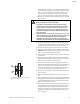
Fig. 43: Δp-c/Δp-v control
Q
s
Hmax
H
H
s
Hmin
Hs
1
2
Q
H
H
Q
H
max
H
s
H
min
H
s
1
2
Setting (Fig. 43) Δp-c Δp-v
Duty point on
maximum pump
curve
Draw from duty point
towards the left. Read
off setpoint H
S
and set
the pump to this value.
Draw from duty point
towards the left. Read
off setpoint H
S
and set
the pump to this value.
Duty point
within the con-
trol range
Draw from duty point
towards the left. Read
off setpoint H
S
and set
the pump to this value.
Move to max. pump
curve along control
curve, then horizontally
to the left, read off set-
point H
S
and set the
pump to this value.
Adjustment
range
H
min
, H
max
see pump curves
(in catalogue, select or
online)
H
min
, H
max
see pump curves
(in catalogue, select or
online)
1
2
Fig. 44: Manual control mode
Q
H
H
Q
n
min
n
max
s
H
s