
User Guide

English
Installation and operating instructions Wilo-Stratos GIGA 15
The emergency operation speed can be set in menu <5.6.2.0> (see
chapter 6.3.3 on page 17).
• The master's display will show the status of the double pump. On the
slave display, 'SL' will appear.
• The master pump is the left pump in the direction of flow.
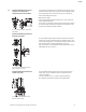
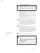
Connect the differential pressure sensor to this pump.
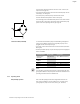
The measuring points of the differential pressure sensor of the master
pump must be on the suction and pressure side of the double-pump
system in the corresponding collector pipe (Fig. 18).
InterFace module (IF-Module) For communication between pumps and the building management
system, one IF-Module (accessories) is required per pump. This is
plugged into the terminal space (Fig. 1).
• The master-slave communication uses an internal interface (terminal:
MP, Fig. 26).
• Normally for double pumps, only the master pump must be equipped
with an IF-Module.
NOTE:
The procedure and further information for commissioning and confi-
guring the IF-Module on the pump can be found in the installation and
operating instructions of the IF-Module used.
6.3.1 Operating modes
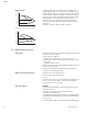
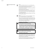
Main/standby operation Each of the two pumps provides the configuration flow rate. The
other pump is available in case of malfunction or runs after pump
cycling. Only one pump runs at a time (see Fig. 15, 16 and 17).
Fig. 18: Example, DDG connection
Communication Master pump Slave pump
PLR/Interface
converter
IF-Module PLR No IF-Module necessary
LONWORKS
network
IF-Module LON No IF-Module necessary
BACnet
BACnet IF-Module No IF-Module necessary
Modbus Modbus IF-Module No IF-Module necessary
CAN bus
CAN IF-Module No IF-Module necessary