Wilo-Stratos GIGA en Installation and operating instructions fr Notice de montage et de mise en service 2 122 060-Ed.
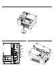
Fig. 1: IF-Modul Fig. 3: 3 NPT M25 /4” GND In1 1 XXXXXXXXXXXXXXXXX NPT M161/4” Option IF-/LON-Modul 1 NPT M16/4” IF-Modul LON-Modul TERM MP O O O 1 1 S AUX Ext.off L MP H In2 NPT M201/2” 10V/20mA GND +24V 2 3 DDG SBM SSM L1 L2 L3 Fig. 2: M12x1.
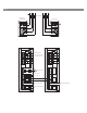
Fig. 4: max. 20 A RK5 Single pump MA Twin pump SSM SSM L1 L1 L2 L2 L3 L3 SL Twin pump external supply min. 12 V DC / 10 mA SBM 2 3 DDG 1 external off (switch) Ext.off pump swamp (button) AUX L 10V /20mA 2 3 DDG Ext.off MP H 10 V / 20 mA In2 GND In1 GND +24V external value MP 10V /20mA 1 pressure sensor AUX L H In2 GND In1 GND +24V SBM max.
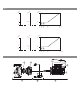
Fig. 5: [%] 100 0 off [ft] Δpmax [1/min] nmax Δpmin nmin 0 0 0 2 [%] 100 0 off [ft] Δpmax [1/min] nmax Δpmin nmin 0 1,0 2,8 1,5 3,2 4,0 5,2 2,0 5,6 3,0 6,4 8,0 10,4 10 [V] 10 0 0 4 20 [mA] 20 Fig.
13 14 15 16 13 17 18 12 11 19 10 20 21 9 8 7 20a 6 20b 5 4 22 3 2 1 Fig.
en Installation and operating instructions fr Notice de montage et de mise en service es Instrucciones de instalación y funcionamiento 2 66 134
English 1 2 General notes ........................................................................................................................................ 3 Safety ..................................................................................................................................................... 3 2.1 2.2 2.3 2.4 2.5 2.6 2.7 2.8 Symbols and signal words used in these operating instructions ....................................................................
English 1 General notes Installation and operating instructions About this document These Installation and Operating Instructions form an integral part of the product. They must be kept close to the product and in readiness whenever required. Precise observance of these instructions is a precondition for use of the product for the intended purpose and for its correct operation.
English NOTE: A notice with useful information for the user in relation to the product. It attends the user to possible problems. • • • • Information applied directly to the product, such as: direction of rotation arrow, identifiers for connections, name plate, and warning sticker, must be strictly complied with and kept in legible condition. 2.2 Qualified Personnel The personnel installing the pump must have the appropriate qualifications for this work.
English 2.6 Safety precautions for inspection and installation The operator must ensure that all inspection and installation work is carried out by authorized and qualified specialists who have carefully reviewed these instructions. Work on the pump/unit must be carried out only with the pump disconnected (locked out) from the electrical supply and at complete standstill.
English 3.2 Transport for installation/ dismantling purposes WARNING! Risk of injuries to personnel! Incorrect transport can cause injury to personnel. • The pump must be transported using approved load-bearing equipment (e.g. block and tackle, crane, etc.). These are to be attached to the transport eyes at the motor flange (Fig. 8, shown here: lifting direction with vertical motor shaft). • If necessary, e.g.
English NOTE: Swivel/turn the transport eyes to improve the balance in accordance with the direction of lifting. To do this, loosen and then retighten the fastening screws. WARNING! Danger of personal injury! Setting up the pump without securing it can lead to personal injury. • Do not place the pump unsecured on the pump base. The base with the threaded holes is only used for attachment. When standing freely, the pump might not be sufficiently stable.
English WARNING! Danger of personal injury! Opening the motor leads to high, suddenly occurring magnetic forces. These can cause serious cuts, crushing injuries and bruises. • Do not open the motor! • Only allow Wilo customer service to dismantle and install the motor flange and the end shield for maintenance and repair work. CAUTION! Danger of property damage! Unpermitted substances in the fluid can destroy the pump. Abrasive solids (e.g. sand) increase pump wear.
English 5.2 Technical data Property Value Remarks Speed range 500 - 5130 rpm 1.5/2/2.5 in Flanges acc.
English NOTE: The flow value shown on the IR-Monitor display or output to the building management system must not be used to control the pump. This value is merely an indicator of general trends. A flow value is not an output on every type of pump. NOTE: Always read and follow the material safety data sheet for the fluid being pumped! 5.3 Scope of delivery 5.
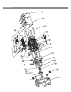
English Main components Fig. 7 shows an exploded drawing of the pump with the main components. In the following, the assembly of the pump is explained in detail. Arrangement of the main components in accordance with Fig. 7 and Tab. 1: No.
English Name plates The Wilo-Stratos GIGA has three name plates: • The pump name plate (Fig. 11, Item 1) includes the serial number (Ser.-No…/…), which is, for example, required for spare parts ordering. • The electronic module name plate (electronic module = inverter or frequency converter) (Fig. 11, Item 2) indicates the designation electronic module being used. 2 1 Fig.
English For the following purposes, the motor impeller unit can be separated from the pump housing (which can remain in the piping) (also see chapter 10 “Maintenance” on page 48): • To provide access to the inside parts (impeller and mechanical seal) • To make it possible to separate the motor from the hydraulic unit. 1 2 When this is done, the transport eyes (Fig. 13, Item 2) are removed from the motor flange (Fig.
English HH Δp-v: The electronics linearly change the differential pressure setpoint to be kept by the pump between the delivery heads Hs and ½ Hs. The differential pressure setpoint Hs decreases or increases with the volume flow (Fig. 16). Hmax Hs ½ Hs Hmin Q Q Fig. 16: Δp-v control Q = Volume flow H = Differential pressure (min./max.
English The emergency operation speed can be set in menu <5.6.2.0> (see chapter 6.3.3 on page 17). • The master's display will show the status of the double pump. On the slave display, 'SL' will appear. • The master pump is the left pump in the direction of flow. Connect the differential pressure sensor to this pump. The measuring points of the differential pressure sensor of the master pump must be on the suction and pressure side of the double-pump system in the corresponding collector pipe (Fig. 18).
English Parallel operation In the partial load range, the hydraulic output is provided at the beginning by one pump. The second pump will be switched on when it is most effective to do this, i.e. when the total power consumptions P1 of both pumps in the partial load range is less than the power consumption P1 of one pump. Both pumps will then be simultaneously adjusted upwards to the maximum speed (Fig. 19 and 20). H Hmax Hs s Hmin Q In manual control mode, both pumps always run synchronously.
English EBM/SBM: • A collective run signal (SBM) can be connected to the master for a central control center. • In this case, the contact may only be made to the master. • The display is for the whole unit. • This signal can be programmed on the IR-Monitor as an individual run signal (EBM) or collective run signal (SBM) (menu <5.1.6.0>). • The functions – “Readiness”, “Operation”, “Mains on” – from EBM/ SBM can be set at <5.7.6.0> at the master.
English NOTE: In the absence of a sensor signal, the (former) slave will run at maximum speed. To prevent this, the (former) master's differential pressure sensor signal can be looped through. When the double pump is operating normally, it is not affected by sensor signals pending on the slave.
English Behavior after being switched on The pump operates with its factory settings in initial commissioning. • The service menu deals with the setting and converting of individual pumps; see chapter 8 “Operation” on page 29. • To correct faults, also see chapter 11 “Faults, causes and remedies” on page 57. CAUTION! Danger of personal damage! Modifying the settings for the differential pressure sensor can lead to malfunctions.
English DANGER! Danger of death! Failure to install safety devices of the electronic module and the motor can cause electrical shock or contact with rotating parts, potentially resulting in life-threatening injuries. • Before commissioning, all safety devices such as module covers or fan covers that were removed must be reinstalled. DANGER! Danger of death! Deadly danger due to module not being installed! Fatal voltages can be present at the motor contacts.
English 7.1 Permitted installation positions and change of the arrangement of components before the installation The component arrangement concerning the pump housing is preinstalled as a factory setting (see Fig. 21) and can be changed if need be at the operating location. This can be necessary, for example, to: • Ensure the bleeding of the pumps • Make operation easier • Prevent impermissible installation positions (i.e.
English Changing the component arrangement • • • • NOTE: To make the installation work easier, the “dry” installation of the pump in the piping can be helpful, e.g., installation without electrical connection and without filling of the pump or system. Carry out steps 5 to 10 in accordance with chapter 10.2.1 “Replacing the mechanical seal” on page 50. Rotate the motor impeller unit by 90° or 180° in the desired direction and install the pump in the reverse order.
English 7.2 Installation Preparation • The pump should only be installed following completion of all welding and soldering work and, if necessary flushing of the pipe system. Dirt can cause pump failure. • The pumps must be protected from the weather and installed in a frost/dust-free, well-ventilated environment which is not potentially explosive. The pump must not be installed outdoors. • Install the pump in a place that is easy to access so that subsequent inspections, maintenance (e.g.
English CAUTION! Danger of property damage! A volume flow going against or with the direction of flow (turbine operation or generator operation) can cause irreparable damage to the drive. • A non-return valve shall be installed on the pressure side of each pump. • The pipes and pump must be free of mechanical stress when installed. The pipes must be fastened in such a way that the pump does not bear the weight of the pipes.
English DANGER! Danger of death! For generator operation or turbine operation of the pump (rotor drive), there may be a dangerous contact voltage at the module's contacts. • Close the shut-off device in front of and behind the pump. DANGER! Danger of death! Contact voltage can be life-threatening. Work on the module may only be started after waiting five minutes, due to the dangerous residual contact voltage (capacitors). • Before working on the pump, disconnect the power supply and wait for five minutes.
English • The electrical connection must be established via a fixed power cable which has a plug attachment or an all-pole switch with a contact opening width of at least 1/8” (3 mm). Use 140/167 °F (60/75 °C) copper conductors only. The power cable is to be fed through the NPT 3/4 “ threaded cable connection (Fig. 25, Item 1). Cross-section of power cable to be maintained: min. AWG16 (4 x 1.5 mm2) max. AWG12 (4 x 4.0 mm2) 1 Fig.
English • Take additional grounding into account! • The use of a time delay fuse is recommended. • Internal overload protection operates prior to reaching the 110% of the motor full load. Terminals See following table for assignment. For details see wiring diagram (Fig. 4). 2 3 DDG 1 10V /20mA MP AUX Ext.off L H In2 GND In1 GND +24V SBM SSM • Control terminal (Fig. 26). Fig. 26: Control terminals • Power terminals (mains connection terminals) (Fig. 27).
English Connection terminal allocation Designation Assignment Notes L1, L2, L3 Ground Mains connection voltage Protective conductor connection Actual value input Three-phase current 3~380 V to 3~480 V AC, 50/60 Hz, IEC 38 IN1 (1) (input) Type of signal: Voltage (0-10 V, 2-10 V) Input resistance: Ri ≥ 10 kΩ Type of signal: Current (0-20 mA, 4-20 mA) Input resistance: Ri = 500 Ω IN2 (input) Setpoint input Can be configured in the service menu <5.3.0.
English NOTE: The control is designed as a PELV (protective extra low voltage) circuit, meaning that the (internal) supply meets the requirements for safe supply isolation; the GND is connected to M (Ground) Differential pressure sensor connection Cable Colour Terminal Function 1 2 3 black blue brown IN1 GND +24 V Signal Ground +24 V NOTE: The electrical connection of the differential pressure sensor is to be fed through the smallest threaded cable connection (M12) on the module.
English 8.2 Display structure Information appears on the display as shown in the sample illustration below: 1 1 0 0 0 4 20 0 0 5 max min 4 R P M 2 Fig. 30: Display structure Item Description Item Description 1 2 3 4 5 Menu number Value display Units display Standard symbols Symbol display NOTE: The display can be rotated by 180°. To change, see menu number <5.7.1.0 >. 8.
English 8.4 Symbols in graphics/instructions Chapter 8.6 “Operating instructions” on page 34 contains graphics that illustrate the operating concept and provide instructions for configuring settings. In the graphics and instructions, the following symbols are used as simple representations of menu elements or actions: Menu elements 12.3 4.1.0.0 4.4.3.0 2.0.0.0 ± • Menu status page: Standard view on the display. • “One level down”: A menu element that can be used to jump to a lower menu level (e.g.
English 8.5.1 Display status page 12.3 The standard view on the display is the status page. The current setpoint is displayed in the number segments. Other settings are displayed using symbols. NOTE: For dual pump operation, the operating mode is also shown in symbol format on the status page (“Parallel operation” or “Main/reserve”). The display of the slave pump shows 'SL'. 8.5.2 Display menu mode The electronic module functions can be called via the menu structure.
English “Selection/setting” menu element ± The “Selection/setting” menu element does not have a special label on the display, but is identified graphically in these instructions by the adjacent symbol. If a “Selection/setting” menu element is selected, pressing the red button will change to edit mode. In edit mode, flashing values can be changed by turning the red button. In some menus, acceptance of the input by pressing the red button will be confirmed by the brief display of the 'OK' symbol. 8.5.
English Access disable menu The main menu <7.0.0.0> is only displayed when DIP switch 2 is in the ON position. It cannot be reached via normal navigation. In the “Access disable” menu, the access disable can be activated or deactivated by turning the red button. The change is confirmed by pressing the red button. 8.6 Operating instructions 8.6.1 Adjusting the setpoint On the status page of the display, the setpoint can be adjusted as follows (Fig. 33): • Turn the red button. 1.0.0.0 12.
English 8.6.3 Navigation 1.0.0.0 2.0.0.0 2s ± • Change to menu mode (see 8.6.2 “Changing to menu mode” on page 34). Carry out general menu navigation as follows (for an example, see Fig. 37): ± During navigation, the menu number flashes. • To select the menu element, turn the red button. 4.0.0.0 4.1.0.0 5.0.0.0 4.2.0.0 4.4.0.0 4.4.1.0 4.4.3.0 The menu number is incremented up or down. The symbol associated with the menu element and the setpoint or actual value are shown, if applicable.
English 12.3 2.0.0.0 ± NOTE: When values are changed under <1.0.0.0>, <2.0.0.0> and <3.0.0.0>, <5.7.7.0> and <6.0.0.0>, the display jumps back to the status page (Fig. 39). 2.0.0.0 2.0.0.0 2.0.0.0 Fig. 39: Setting with return to the status page 8.6.5 Calling up information 12.3 4.1.0.0 Changes cannot be made in “Information” menu elements. These are identified on the display by the default “access disable” symbol.
English 8.6.7 Activating/deactivating access disable In order to prevent impermissible changes to the pump settings, all functions can be disabled. When access is disabled, this is shown on the status page by the default “access disable” symbol. ON 2 To activate or deactivate this, proceed as follows: • Set DIP switch 2 to the 'ON' position. Menu <7.0.0.0> is displayed. • Turn the red button to activate or deactivate the disable. • To confirm the change, press the red button.
English The condition for hiding a menu element is explained in the last column of the table. No. Designation Type 1.0.0.0 Setpoint ± 2.0.0.0 Control mode ± Symbol Values/explanations Display conditions Setting/display of the setpoint (for further information, see chapter 8.6.1 “Adjusting the setpoint” on page 34) Setting/display of the control mode (for further information, see chapters 9.4 “Setting the control mode” on page 47 and 6.
English No. Designation Type Symbol Values/explanations 4.2.2.0 Consumption Energy consumption in kWh/MWh 4.2.3.0 Countdown, pump cycling Time to pump cycling in h (at a resolution of 0.1 h) 4.2.4.0 Remaining time until pump exercise 4.2.5.0 Mains on counter 4.2.6.0 Pump exercise counter Time until the next pump exercise (after the pump has had a 24 h standstill (e.g. via Ext.
English No. Designation Type Symbol Values/explanations Display conditions SBM Run signal SBM Readiness signal SBM Mains on signal 4.3.4.0 Ext. Off Signal present at the input “Ext. off” OPEN Pump is switched off SHUT Pump is enabled for operation 4.3.5.0 4.4.0.
English No. Designation Type Symbol Values/explanations Display conditions 4.4.1.0 Pump name 4.4.2.0 Software version of user controller Example: Only the basic pump model Stratos GIGA 1.5/3-165 appears on the display; ver(display in ticker format) sion names are not shown. Displays the software version of the user controller. 4.4.3.
English No. Designation 5.2.0.0 Type BMS 5.2.1.0 LON/CAN/IFModul Wink/service ± 5.2.2.0 Local/remote operation ± Symbol Values/explanations Settings for Building Management System (BMS) – building automation The wink function permits the identification of a device in the BMS network. A "wink" is executed by confirmation. BMS local operation Display conditions Incl.
English No. Designation Type 5.5.1.0 P parameter 5.5.2.0 I parameter 5.5.3.0 D parameter ± ± ± 5.6.0.0 5.6.1.0 Error HV/AC Symbol Values/explanations Display conditions Setting of the proportional term of the control Setting of the integral term of the control Setting of the derivative term of the control Settings for behavior in case of error ± HV “heating” mode AC “cooling/air-conditioning” mode 5.6.2.0 Emergency operation speed 5.6.3.0 Auto reset time 5.7.0.0 5.7.1.
English No. 9 Designation Type 6.0.0.0 Error acknowledgment ± 7.0.0.0 Access disable ± Symbol Values/explanations ON Confirming will reset the settings to factory settings. Caution! All manual settings will be lost. For additional information, see chapter 11.3 “Acknowledging errors” on page 59. “Access disable” inactive (changes possible) (for further information, see chapter 8.6.7 “Activating/deactivating access disable” on page 37).
English 1 • To avoid cavitation noise and damage, a minimum inlet pressure must be guaranteed at the suction port of the pump. This minimum inlet pressure depends on the operating situation and the duty point of the pump, and must be defined accordingly. • The main parameters for defining the minimum intake pressure are the NPSH of the pump at its duty point and the vapor pressure of the fluid. • Bleed the pumps by releasing the bleed valves (Fig. 41, Item 1).
English 9.2 Double pump installation/Y-pump installation NOTE: For the initial commissioning of a Y-pump installation that has not been preconfigured, both pumps are set to their factory setting. After connecting the double pump communication cable, the fault code 'E035' is displayed. Both drives run at the emergency operation speed. On acknowledgment of the error message, menu <5.1.2.0> is displayed and 'MA' (= master) flashes.
English 9.4 Setting the control mode Δp-c/Δp-v control: Setting (Fig. 43) Δp-c H Hmax 1 Hs 2 Hs 1 s Hmin 2 Q HH Duty point on Draw from duty point maximum pump towards the left. Read curve off setpoint HS and set the pump to this value. Draw from duty point Duty point within the con- towards the left. Read off setpoint HS and set trol range the pump to this value. Hmax 1 2 Adjustment range Hs Hs Hmin Q Q Fig.
English meter values should only be tuned by someone with training in control engineering. Control portion Factory setting Adjustment range Increment P 0.5 I 0.5 s D 0 s (= deactivated) 0.1 0.01 0.01 0.1 10 ms 1s 10 ms 1s -30.0 -1.99 0.00 2.0 10 ms 1s 0 ms 1s ... -2.0 ... -0.01 ... 1.99 ... 30.0 ... 990 ms ... 300 s ... 990 ms ... 300 s The direction of action of the controller is determined by the sign of the P term.
English DANGER! Danger of death! The permanently magnetized rotor inside the motor presents an acute danger to persons with pacemakers. Non-observance results in death or very serious injuries. • Do not open the motor! • Only allow Wilo customer service to dismantle and install the rotor for maintenance and repair work. WARNING! Danger of personal injury! Opening the motor leads to high, suddenly occurring magnetic forces. These can cause serious cuts, crushing injuries and bruises.
English DANGER! Danger of death! The tools used during maintenance work on the motor shaft (such as an open-end wrench) can be flung out if they come into contact with rotating parts and cause serious or even fatal injuries. • The tools used during maintenance work must be removed completely before the pump is started up. • If the transport eyes are moved from the motor flange to the motor housing, they must be resecured to the motor flange following the installation or maintenance work. 10.
English 6. Depressurize the pump by opening the bleed valve (Fig. 45 Item 1). 1 7. Loosen the screws (Fig. 7, Item 1) and pull off the fan cover (Fig. 7, Item 2) axially from the motor. 8. The spacers are to be turned out of the two drilled holes of the transport eyes (Fig. 7, Item 20b). Be sure to keep the spacers or screw them into the empty drilled holes after moving the transport eyes (see step 9) (Fig. 7, Item 20a). 9. Remove the two transport eyes (Fig. 7, Item 20) from the motor flange (Fig.
English 13. Press the motor impeller unit (see Fig. 13) off the pump housing. It is a good idea to use two threaded holes (Fig. 47, Item 1) for this; particularly to loosen the seating. Screw two suitable screws into the threaded holes to loosen the seating. If the motor impeller unit can be moved easily, slots (Fig. 47, Item 2) between the pump housing and the lantern can also be used for pressing off (for example, use two screwdrivers as levers to do this). After pressing out about 0.
English when doing this (see chapter 7.1 “Permitted installation positions and change of the arrangement of components before the installation” on page 21). Attach the lantern with the screws (Fig. 7, Item 10) or – for the pump/lantern types in accordance with (Fig. 46) – with the screws (Fig. 46, Item 8) at the motor flange. 23. Push the new rotating unit of the mechanical seal (Fig. 7, Item 12) onto the shaft. CAUTION! Danger of property damage! Danger of damage due to incorrect handling.
English The use of mounting bolts is recommended (see chapter 5.4 “Accessories” on page 10). After the lantern guide has been firmly locked into place (about 0.6 in/15 mm) before the end position), there is no longer any danger of tipping or canting. After the motor impeller unit has been secured with at least one screw (Fig. 7, Item 3), the attaching material can be removed from the transport eyes. 34. Screw in the bolts (Fig. 7, Item 3) but do not tighten them all the way.
English Screw tightening torques Part Fig./Item Screw (nut) Thread Screw head Type... Tightening Installation torque information lbf.ft ± 10% / lb.in ± 10% (Nm ± 10%) (if not otherwise specified) (1 ft = 12 in) Transport eyes Fig. 7/Item 20 M8 Hexagon socket 0.25 in (6 mm) 15/180 (20) Fig. 7/Item 3 Motor impeller unit Fig. 44/Item 3 M12 Hexagon socket 0.4 in (10 mm) 44/528 (60 ) Fig. 7/Item 10 Fig. 44/Item 8 M6 M10 Hexagon socket 0.2 in (5 mm) Hexagon socket 0.
English 10.2.2 Replacing the motor • Carry out steps 1 to 19 to dismantle the motor in accordance with chapter 10.2 “Maintenance work” on page 50. • Remove the screws (Fig. 7, Item 21) and pull the electronic module vertically upwards (Fig. 7). • Before reinstalling the electronic module, pull the new O-ring between the module (Fig. 7, Item 22) and the motor (Fig. 7, Item 4) onto the contacting chamber. • Press the electronic module into the contacting of the new motor and fasten with screws (Fig.
English • The fan wheel has to be pressed on as far as possible when it is installed. Only press here in the area of the hub. 11 Faults, causes and remedies Have faults remedied by qualified personnel only! Observe the safety instructions in chapter 10 “Maintenance” on page 48. • If the malfunction cannot be rectified, consult a specialist technician or the nearest customer service or representative office.
English 11.2 Error table Classification No.
English Classification No. Communica- E050 tion error E051 E052 Electronics faults E070 E071 E072 E076 E077 E096 E097 E098 E110 System errors 11.
English NOTE: A 30-second time-out causes the display to revert to the status page or error page. NOTE: Every error number has its own error counter, which counts the incidence of the error within the last 24 hours and is reset after manual acknowledgment, 24-hour continuous “mains on” or a new “mains on”. 11.3.1 Error type A or D Error type A (Fig.
English If type A or D errors occur, proceed as follows to acknowledge (Fig. 53): • To change to menu mode, press the red button. 6.0.0.0 E000 Menu number <6.0.0.0> flashes on the display. • Press the red button again. Menu number <6.0.0.0> appears steady on the display. 6.0.0.0 60S 1/1 The time remaining until the error can be acknowledged is displayed. • Wait until the remaining time is up. 6.0.0.0 The time until manual acknowledgment is always 60 seconds for error types A and D.
English Incidence X < Y E000 If the current incidence of the error is less than the maximum incidence (Fig. 55): • Wait for auto reset time. 6.0.0.0 On the value display, the remaining time until auto reset of the error is displayed in seconds. After the auto reset time has run out, the error will be automatically acknowledged and the status page will be displayed. 6.0.0.0 75S 3/6 12.3 Fig. 55: Acknowledge error type B (X < Y) NOTE: The auto reset time can be set on menu number <5.6.3.
English 11.3.3 Error type C Error type C (Fig. 57): Program Contents step/query 1 1 2 2 3 4 5 6 7 8 3 4 5 • Error code is displayed • Motor off • Red LED on Error criterion fulfilled? > 5 minutes? • Error counter is incremented Error counter > 5? • SSM is activated Error acknowledged? End; auto control resumes yes no 6 7 8 Fig. 57: Error type C, diagram E000 If type C errors occur, proceed as follows to acknowledge (Fig. 58): • To change to menu mode, press the red button. 6.0.0.
English 11.3.4 Error type E or F Error type E (Fig. 59): Program Contents step/query 1 1 2 2 3 4 5 6 7 8 9a 3 4 5 9b • Error code is displayed • Pump goes into emergency operation • Error counter is incremented Error matrix AC or HV? • SSM is activated Error criterion fulfilled? Error acknowledged? Error matrix HV and > 30 minutes? • SSM is activated End; auto control (double pump) resumes End; auto control (single pump) resumes yes no 6 7 8 9a 9b Fig.
English If type E or F errors occur, proceed as follows to acknowledge (Fig 61): • To change to menu mode, press the red button. 6.0.0.0 E000 12.3 Fig. 61: Acknowledge error type E or F Menu number <6.0.0.0> flashes on the display. • Press the red button again. The error is acknowledged, and the status page is displayed. NOTE: The error will be acknowledged automatically if the cause of the error is eliminated.