
User Guide

English
Installation and operating instructions Wilo-Stratos GIGA 21
7.1 Permitted installation positions and
change of the arrangement of
components before the installation
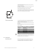
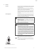
The component arrangement concerning the pump housing is prein-
stalled as a factory setting (see Fig. 21) and can be changed if need be
at the operating location. This can be necessary, for example, to:
• Ensure the bleeding of the pumps
• Make operation easier
• Prevent impermissible installation positions (i.e. motor and/or elec-
tronic module downwards)
In most cases, it is enough to rotate the motor impeller unit relative to
the pump housing. The possible arrangement of components is the
result of the permitted installation positions.
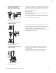
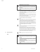
Permitted installation positions with
horizontal motor shaft
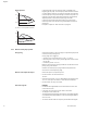
The permitted installation positions with horizontal motor shaft are
shown in Fig. 22. Any installation position is allowed except for “elec-
tronic module facing down”. The venting of the pump is only ensured
when the bleed valve is pointing upwards (Fig. 22, Item 1).
Only in this position can condensate be directed away and into a pro-
vided drilled hole (Fig. 22, Item 2).
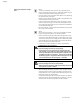
Permitted installation positions with
vertical motor shaft
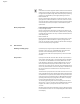
The permitted installation positions with vertical motor shaft are
shown in Fig. 23. Any installation position is allowed except for
“motor facing down”.
The motor impeller unit can – relative to the pump housing –
be arranged in four different positions (each shifted by 90°).
Fig. 21: Arrangement of the components
upon delivery
Fig. 22: Permitted installation positions
with horizontal motor shaft
1
2
Fig. 23: Permitted installation positions
with vertical motor shaft
4 x 90°