
User Guide

English
30 WILO SE 06/2011
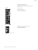
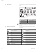
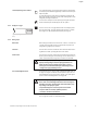
8.2 Display structure Information appears on the display as shown in the sample illustration
below:
NOTE:
The display can be rotated by 180°. To change, see menu number
<5.7.1.0 >.
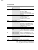
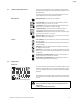
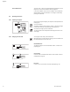
8.3 Explanation of standard symbols The following symbols are shown on the display at the positions
shown above:
Fig. 30: Display structure
Item Description Item Description
1 Menu number 4 Standard symbols
2 Value display 5 Symbol display
3
Units display
max
min
2
1
5
2
3
4
4
4
1000
0002
RPM
Symbol Description Symbol Description
Constant speed control Min operation
Constant control
Δp-c
Max. operation
variable control
Δp-v
Pump is running
PID control Pump is stopping
Input In (external setpoint)
activated
Pump running in emergency operation
Access disable Pump stops in emergency operation
BMS (Building Management System) is
active
DP/MP operating mode: Main/reserve
DP/MP operating mode:
Parallel operation
-
min
max
2