
User Guide

English
Installation and operating instructions Wilo-Stratos GIGA 29
NOTE:
The control is designed as a PELV (protective extra low voltage) cir-
cuit, meaning that the (internal) supply meets the requirements for
safe supply isolation; the GND is connected to M (Ground)
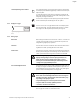
Differential pressure sensor
connection
NOTE:
The electrical connection of the differential pressure sensor is to be
fed through the smallest threaded cable connection (M12) on the
module.
For a double pump or Y-pump installation, the differential pressure
sensor is to be connected to the master pump.
The measuring points of the differential pressure sensor of the master
pump must be on the suction and pressure side of the double-pump
system in the corresponding collector pipe.
Procedure • Establish connections observing the terminal allocation.
• Ground the pump/system according to regulations.
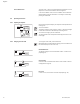
8Operation
8.1 Operating elements The electronics module is operated using the following operating ele-
ments:
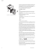
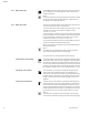
The red button
The red button (Fig. 28) can be turned to select menu elements and
used to change values. Pressing the red button activates a selected
menu element and confirms values.
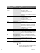
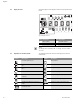
DIP switch
The DIP switches (Fig. 14, Item 5/Fig. 29) are located under the hous-
ing cover.
• Switch 1 is for switching between the standard and service mode.
For additional information, see chapter 8.6.6 “Activating/deactivating
service mode” on page 36.
• Switch 2 allows activation or deactivation of the “access disable” fea-
ture.
For additional information, see chapter 8.6.7 “Activating/deactivating
access disable” on page 37.
• Switches 3 and 4 permit termination of the multi-pump communica-
tion.
For additional information, see chapter 8.6.8 “Activating/deactivating
termination” on page 37.
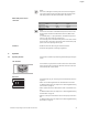
Cable Colour Terminal Function
1black IN1 Signal
2blue GND Ground
3 brown +24 V +24 V
Fig. 28: The red button
Fig. 29: DIP switch
1234
ON