
User Guide

English
Installation and operating instructions Wilo-Stratos GIGA 11
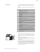
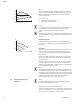
Main components Fig.
7
shows an exploded drawing of the pump with the main compo-
nents. In the following, the assembly of the pump is explained in
detail.
Arrangement of the main components in accordance with Fig.
7
and
Tab. 1:
Tab. 1: Arrangement of the main components
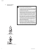
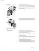
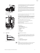
The typical characteristic of the Stratos GIGA series is the jacket cool-
ing of the motor. The air current is optimally conducted by the long
fan cover (Fig. 10, Item 1) for cooling the motor and the electronic
module.
(Fig. 10, Item 2) shows the pump housing with a special lantern chan-
nel to reduce the load of the impeller.
The transport eyes (Fig. 10, Item 3) are to be used in accordance with
chapters 3 and 10.
The window in the lantern that is covered with the protective plate
(Fig. 10, Item 4) is used for maintenance work in accordance with
chapter 10 “Maintenance” on page 48. The window can also be used
to check for leaks with consideration of the safety regulations in
accordance with chapter 9 “Commissioning” on page 44 and chapter
10 “Maintenance” on page 48.
No. Part
1 Fastening screws of the fan cover
2 Fan cover
3
Motor impeller unit fastening screws
4 Motor housing
5 Differential pressure sensor (DDG)
6
DDG holder
7 Motor flange
8 Motor shaft
9
Lantern
10 Fastening screws of the lantern
11 O-ring
12
Rotating unit of the mechanical seal (mechanical seal)
13
Pressure measuring line
14 Pump housing
15 Impeller nut
16
Impeller
17 Counter ring of the mechanical seal
18 Protective plate
19
Bleed valve
20 Transport eye
20a Attachment points for transport eyes at the motor flange
20b
Attachment points for transport eyes at the motor housing
21 Fastening screws of the electronic module
22 Electronic module
Fig. 10: Pump assembly
1
2
4
3