
User Guide

English
28 WILO SE 06/2011
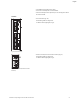
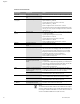
Connection terminal allocation
NOTE:
The terminals IN1, IN2, AUX, GND, Ext. Off and MP meet the require-
ment for “isolated secondary circuits, limited voltage/limited current”
(according to UL508C and EN 61800-5-1) to the mains terminals, as
well as to the SBM and SSM terminals (and vice versa).
Designation Assignment Notes
L1, L2, L3
Mains connection voltage
Three-phase current 3~380 V to 3~480 V AC, 50/60 Hz, IEC 38
Ground Protective conductor connec-
tion
IN1
(1) (input)
Actual value input Type of signal: Voltage (0-10 V, 2-10 V)
Input resistance: R
i
≥ 10 kΩ
Type of signal: Current (0-20 mA, 4-20 mA)
Input resistance: R
i
= 500 Ω
Can be configured in the service menu <5.3.0.0>
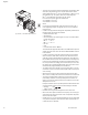
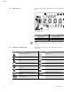
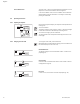
Connected at the factory via the M12 threaded cable connec-
tion (Fig. 2), via (1), (2), (3) according to the sensor cable des-
ignations (1,2,3).
IN2
(input)
Setpoint input IN2 can be used as the input for remote setpoint adjustment
in all operating modes.
Type of signal: Voltage (0-10 V, 2-10 V)
Input resistance: R
i
≥ 10 kΩ
Type of signal: Current (0-20 mA, 4-20 mA)
Input resistance: R
i
= 500 Ω
Can be configured in the service menu <5.4.0.0>
GND (2)
Ground connections For both input IN1 and IN2
+ 24 V (3) (output)
DC voltage for an ext. consumer/
sensor
Max. load 60 mA. The voltage is short-circuit proof.
AUX External pump cycling Pump cycling can be performed using an external, potential-
free contact. One-time bridging of the two terminals will
cause external pump cycling to take place, if it is enabled.
Bridging a second time will cause the procedure to repeat,
provided the minimum run time is adhered to.
Can be configured in the service menu <5.1.3.2>
Contact load: 24 V DC/10 mA
MP
Multi Pump Interface for dual pump function
Ext. Off
Control input “Overriding off”
for external, potential-free
switch
The pump can be switched on/off via an external potential-
free contact.
In systems with a high switching frequency (> 20 on/off oper-
ations per day); switching on/off must take place via “Ext. Off”.
Can be configured in the service menu <5.1.7.0>
Contact load: 24 V DC/10 mA
SBM
Individual run signal/collective
run signal, readiness signal and
mains on signal
Potential-free individual run signal/collective run signal
(changeover contact), operation readiness signal is available
at the SBM terminals (menus <5.1.6.0>, <5.7.6.0>).
Contact load: Permitted minimum: 12 V DC, 10 mA
Permitted maximum: 250 V AC/24 V DC, 1 A.
SSM
Individual/collective fault signal Potential-free single/collective fault signal (changeover con-
tact) is available at the SSM terminals (menu <5.1.5.0>).
Contact load: Permitted minimum: 12 V DC, 10 mA
Permitted maximum: 250 V AC/24 V DC, 1 A.
Interface
IF-Module
Connection terminals of the
serial digital BA interface
The optional IF-Module is pushed into a multi-plug in the ter-
minal box. The connection is twist proof.