
User Guide

English
14 WILO SE 06/2011
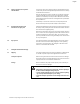
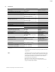
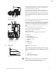
Δp-v:
The electronics linearly change the differential pressure setpoint to
be kept by the pump between the delivery heads H
s
and ½ H
s
. The
differential pressure setpoint H
s
decreases or increases with the
volume flow (Fig. 16).
Q = Volume flow
H = Differential pressure (min./max.)
H
S
= Differential pressure setpoint
NOTE:
For further information about setting the control mode and the asso-
ciated parameters, see chapter 8 “Operation” on page 29 and
chapter 9.4 “Setting the control mode” on page 47.
NOTE:
A differential pressure sensor is needed for the control modes that are
being performed (Δp-c and Δp-v) which sends the actual value to the
electronics.
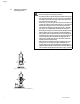
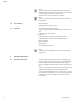
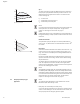
Manual control mode:
The speed of the pump can be kept to a constant speed between n
min
and n
max
(Fig. 17). “Manual control” mode deactivates all other con-
trol modes.
PID control:
If the aforementioned standard control modes cannot be used – e.g.
if other sensors are to be used or the distance to the pump is very
long – then the PID control (Proportional-Integral-Differential con-
trol) is available.
By selecting a good combination of individual control portions, the
operator can ensure fast reacting, constant control without lasting
setpoint deviations.
The output signal of the selected sensor can take any intermediate
value. The respective actual value reached (sensor signal) will be
shown as a percentage (100% = maximum measurement range of the
sensor) on the status page of the menu.
NOTE:
The displayed percentage value only corresponds indirectly to the cur-
rent delivery head of the pump(s). It can be, for example, that the maxi-
mum delivery head has already been reached at a sensor signal < 100%.
For further information about setting the control mode and the asso-
ciated parameters, see chapter 8 “Operation” on page 29 and
chapter 9.4 “Setting the control mode” on page 47.
6.3 Dual pump function/Y-pipe
application
NOTE:
The properties described below are only available if the internal
MP interface (MP = Multi Pump) is used.
• Both pumps are controlled by the master pump.
If one of the pumps malfunctions, the other will run according to the
master's control settings. In case of a total failure of the master, the
slave pump operates at emergency operation speed.
Fig. 16: Δp-v control
Q
H
H
Q
H
max
H
s
½ H
s
H
min
Fig. 17: Manual control mode
Q
H
H
Q
n
min
n
max
s
H
s