INSTALLATION GUIDE & USER MANUAL SOUNDPLUS™ INFRARED LISTENING SYSTEM Model WIR TX925, Two-Channel Listening System Model WIR TX900, Four-Channel Listening System Model WIR SYS 1, Two-Channel Listening System Model WIR SYS 2, Two-Channel Listening System Model WIR SYS 2P, Two-Channel Listening System Model WIR SYS 4, Four-Channel Listening System Williams Sound Two Channel Infrared System Modulator Microprocessor Controlled Frequency Synthesized Power 4 5 6 3 2 1 0 10 Level 7 8 9 3.
SOUNDPLUS™ INFRARED LISTENING SYSTEM, Model WIR TX925, Two-Channel Listening System Model WIR TX900, Four-Channel Listening System Model WIR SYS 1, Two-Channel Listening System Model WIR SYS 2, Two-Channel Listening System Model WIR SYS 2P, Two-Channel Listening System Model WIR SYS 4, Four-Channel Listening System INSTALLATION GUIDE AND USER MANUAL Contents SYSTEM OVERVIEW Page 4 INSTALLATION PROCEDURES • MOD 232 MODULATOR SETUP WIRING & CONNECTIONS FEATURES & CONTROLS CONFIGURATION SETTINGS • TX9 EMITT
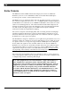
SYSTEM OVERVIEW The Williams Sound SoundPlus™ Infrared Listening System consists of a MOD 232 Modulator(s) and one or more TX9 Emitters which use invisible infrared (IR) light to broadcast speech or music to wireless infrared receivers. The MOD 232 is a two-channel modulator with four selectable frequencies. It accepts two mic or line-level inputs and sends 2.3, 2.8, 3.3, or 3.
MOD 232 Modulator Setup DETERMINE LOCATION The modulator is usually located with the sound system amplifier or mixer for easy access to an audio input signal. For portable systems, the modulator can be placed near the emitter or in another convenient location. Infrared Stand Kits (SS-6, SS-10, SS-11) are available for portable systems. See pages 19-21.
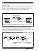
BASEBAND CABLE CONNECTION The MOD 232 can directly drive one or two emitters. TX9 emitters repeat the baseband signal, so any number of emitters can be used. The modulator outputs CANNOT be split with CATV splitters. Determine the length of RG-58 cable needed to reach from the TX9 Emitter to the Modulator unit. Install BNC connectors to each end of the cable (see page 24 for installation details).
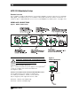
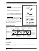
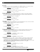
Figure 5: Audio Connection AUDIO CONNECTION MICROPHONE INPUT: With the modulator DIP switches set for microphone input, the 3-pin XLR jack accepts balanced microphones. Power for condenser microphones can be selected by DIP switch. The minimum input level is 100uV and the maximum level is 90 mV. In Phase 1 2 3 3 Pin Connector Balanced Line Using 3–Pin Connector XLR LINE-LEVEL INPUT: With the modulator DIP switches set for line-level input, the 3-pin XLR jack accepts balanced line-level audio inputs.
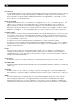
LEVEL INDICATOR The bar graph indicator shows audio level in 3dB steps at the input of the audio level processing circuit. The indicator is peak responding and is calibrated so that optimum level is reached when the amber +3 and +6 lights usually blink and the red +9 light blinks occasionally. Use the level controls to set the audio levels. FREQUENCY (CARRIER) Channel A and B have four “on” indicators to designate 2.3, 2.8, 3.3, or 3.8 MHz frequency.
CONFIGURATION SETTINGS The diagram below (Figure 7) illustrates how to configure your system using the configuration switches (Figure 8) on the back of the MOD 232 Modulator. This diagram is also printed on top of the MOD 232 Modulator unit for quick reference.
MIC/LINE INPUT The MOD 232 only accepts line level balanced or unbalanced inputs on 1/4” TRS phone plug. To setup the MOD 232 to accept line level inputs on the 3 pin XLR connector: Instructions: Place switch 2 in the “off” position. To setup the MOD 232 to accept mic input on 3 pin XLR connector: Instructions: Place switch 2 in the “on” position. MICROPHONE SIMPLEX POWER Most condenser microphones require simplex power to operate. Power can be supplied according to DIN 45596.
AUTO SHUT-OFF TIMER The carriers for each channel shut off automatically if there is no audio for approximately 30 minutes. Audio sufficient to the light the -18 level indicator light will turn the carrier back on immediately. To disable the auto shut-off timer on the MOD 232: Instructions: Place switch 8 in the “off” position. To enable the auto shut-off timer on the MOD 232: Instructions: Place switch 8 in the “on” position. In stereo mode, the timers operate together.
TX9 EMITTER SETUP TX9 LOCATION AND PLACEMENT To determine the best location for the TX9 Emitter, it helps to think of the IR emitter as an invisible floodlight. You’ll want to aim it so the listeners are “flooded” with the infrared light. The emitter should also be positioned high enough so it won’t be blocked by people and other physical obstructions. Mount the emitter at least 2 ft. (.61 m) above the audience.
COVERAGE AREA Determine the coverage area needed for the seating area. When using the TX9 emitter with the RX12-4 receiver, in single channel mode, the TX9 can achieve a coverage area of 28,000 ft2 (2,600 m2 ). In four channel mode, the TX9 divides its power among the four signals to achieve a coverage area of 11,000 ft2 (1,022 m2). NOTE: The coverage area will vary depending on the sensitivity of the infrared receiver being used.
FIG 12: 3-Dimension Foot Pattern The TX9 floods the listening audience with a cone shape light pattern as shown here. The path of the cone shape light leaves a pattern on the ground, or "foot print, " and indicates where the strongest receiver reception will occur. The actual coverage area will vary depending on the sensitivity of the receiver being used. Refer to Figures 11 and 14 to determine how many emitters are required for 100% coverage of the listening area.
FIG 14: Horizontal and Vertical Radiation Polar Plots HORIZONTAL RADIATION POLAR PATTERNS DISTANCE FROM EMITTER TO 1 nW/sq cm CONTOUR 180 48 160 42 140 36 120 30 24 – 70 – 60 – 50 – 40 – 30 100 80 60 200 54 180 48 160 42 140 36 120 30 FEET 54 – 90 – 80 METERS 200 FEET METERS – 90 60 VERTICAL RADIATION POLAR PATTERNS DISTANCE FROM EMITTER TO 1 nW/sq cm CONTOUR – 80 – 70 – 60 – 50 – 40 – 30 100 24 80 18 60 12 40 6 20 – 20 18 60 12 40 6 20 – 20 – 10 – 10
Multiple Emitters Installed to Maximize Coverage FIG. 15a: Overlapping Illumination Patterns to Cover Larger Listening Areas TX9 TX9 TX9 TX9 Fig. 15a above is a typical example of how multiple emitters are used to cover larger listening areas. Generally it is desirable for the illumination patterns to overlap.
MOUNTING THE TX9 TO A WALL OR CEILING Figure 16a: Mounting the TX9 to a wall or ceiling with the BKT 024 TX9 Emitter Swivel Head Shaft (optional) Shaft Plate Cover Mounting Plate (To Wall or Ceiling) Mounting Screws Figure 16b: Mounting the TX9 to a ceiling cross tee with the BKT 024 TX9 Emitter Swivel Head Shaft (optional) Shaft Plate Cover T-Bar Clip (To Suspended Ceiling with Cross Tee) **See page 18 for step-by-step installation instructions.
MOUNTING THE TX9 TO A WALL OR CEILING, STEP-BY-STEP: Figure 17b Figure 17a Figure 17a: Mounting the TX9 on to a wall with the BKT 024. Tip: To keep the TX9 level, rotate the tension screw (Fig. 18) so it rests of top of the bracket. Figure 17b: Mounting the TXP on to a ceiling witth the BKT 024 Step 1: Using the mounting plate (Figure 16a) as a template, mark the hole locations on the mounting surface where the TX9 will be installed. Step 2: Locate the top mounting hole in the rear of the TX9 emitter.
MOUNTING THE TX9 EMITTER AND MOD 232 MODULATOR ON TO A TRIPOD SS-6 Infrared Stand Kit The SS-6 Infrared Stand Kit will hold a single TX9 Emitter and MOD 232 Modulator. The following diagrams (Figures 19a, 19b, & 20) illustrates proper installation when using the SS-6 Infrared Stand Kit. Figure 19a BKT 014 Bracket Butteryfly Screw Figure 19b Grommet Screw (Rubber Insert) STD 004 Top of Tripod Tube Instructions for Use and Care 1.
SS-6 Infrared Stand Kit (cont.
MOUNTING MULTIPLE TX9 EMITTERS ON TO A TRIPOD SS-11 Infrared Stand Kit The SS-11 Infrared Stand Kit can hold up to four TX9 Emitters at one time. The following diagram illustrates proper installation when using the SS-11 Infrared Stand Kit. Figure 21: Mounting the TX9 to the tripod crossbar Knob Extensions (use as need be) Ball and socket Crossbar Top tube of tripod Emitter MOUNTING A SINGLE TX9 ON TO A MIC STAND SS-10 Mic Stand Kit.
TX9 WIRING AND CONNECTIONS FOR U.S. APPLICATIONS: The TX9 Emitter is supplied with a low-voltage wall transformer power supply (TFP 010). Twoconductor 18 ga. zipcord is included with the emitter. FOR U.S. APPLICATIONS OUTSIDE THE U.S. REQUIRING 240 VAC MAINS SUPPLY: Use the transformer power supply, model TFP 027. Secondary Specifications: 24 VAC, 35 VA, 50/60 Hz.
BASEBAND CABLE CONNECTION If you are using ONE emitter: Step 1: Determine the length of RG-58 coaxial cable needed to reach from the emitter to the modulator unit. The modulator is usually located with the other sound equipment to simplify audio connections. 100 feet (30 m) of coaxial cable is included with each emitter. You will need to cut it to length. Additional RG-58 coax can be added. Make sure you leave some slack at each end. Step 2: Install BNC connectors on each end of the cable.
B FIGURE 24A: BNC CONNECTOR ASSEMBLY Washer 7.92 mm (± .25) .312 in. (± .01) Grooved Side Nut Gasket Nut Cable Jacket Washer Plug Assembly Gasket 24C Clamp Contact Clamp positioned against Cable Jacket 24D ASSEMBLY PROCEDURE Clamp Collar The BNC Connector consists of a plug assembly, a contact, a clamp, a gasket, a washer, and a nut. 1. Slide nut, washer and gasket over cable end; then strip outer cable jacket using the recommended strip-length dimension in fig. 24b.
TX9 FEATURES AND CONTROLS POWER INPUT Three-pin connector for TFP 010 (110 VAC) or TFP 027 (for 240 VAC installations) power supply. POWER INDICATOR LED Visible through the bottom panel (Fig. 25). Green indicator light glows when power is on. Note: The TX9 shuts off when no baseband signal is present. BASEBAND INDICATOR LED Visible through the bottom panel (Fig. 25). Red indicator light glows when power is on. BASEBAND IN Connects to the Baseband Out jack of the MOD 232 modulator or another TX9 emitter.
RECEIVER SAFETY INFORMATION HEARING SAFETY CAUTION! This product is designed to amplify sounds to a high volume level which could potentially cause hearing damage if used improperly. To protect your hearing and the hearing of others: 1. Make sure the volume is turned down before putting on the earphone or headphone before adjusting the volume to a comfortable level. 2. Set the volume level at the minimum setting that you need to hear. 3.
OPTIONAL RECEIVER INSTRUCTIONS FOUR CHANNEL RECEIVER, MODEL WIR RX12-4 Make sure the two “eyes” located on the front label of the receiver (Figure 22a) are not covered up when in use. Do not place the receiver in a pocket or purse or it will not work properly. A variety of earphones, headphones, or a neckloop telecoil coupler can be used with the RX12-4 Receiver. Step 1: To install the batteries, open the battery compartment using a coin in the slot in the bottom of the receiver.
TWO CHANNEL RECEIVER, MODEL WIR RX14-2 Step 1: Turn the receiver’s Power Switch to ON Step 2: Place the headset on your head and adjust the headband size by pulling or pushing on each earpiece. Step 3: Locate and adjust the individual volume controls for a comfortable listening level. Step 4: Choose between 2.3 MHz or 2.8 MHz operation by pressing the frequency selector button on the left earphone. NOTE: Be sure the infrared transmitter being used is transmitting on 2.3 MHz or 2.
TROUBLE SHOOTING NEITHER TX9 INDICATOR LIGHT IS ON. Make sure the transformer is plugged into the emitter and any remote power switch is on. Make sure the electrical outlet is on. Make sure the 24 VAC power supply is working. ONLY TX9’S POWER INDICATOR LED COMES ON. Make sure the MOD 232 is on. Make sure the baseband cable is connected properly. See Figures 3 & 4. Check to see if the carrier light on the MOD 232 is on. Make sure an audio signal is being sent to the MOD 232.
SIMULTANEOUS LANGUAGE INTERPRETATION: IC-1 INTERPRETER’S CONTROL CENTER Figure 28 below illustrates a typical four-channel setup using the IC-1 Control Center. Each interpreter monitors the floor signal independently via the “Floor In” connection. To transmit the interpreted message to the listener, the interpreter selects the “Norm” push button on the IC-1 to send their mic signal to the MOD 232 Modulator.
Limited Warranty Williams Sound products are engineered, designed, and manufactured under carefully controlled conditions to provide you with many years of reliable service. Williams Sound warrants the Sound Plus™ Infrared Listening System against defects in materials and workmanship for FIVE (5) years. During the first five years from the purchase date, we will promptly repair or replace the Sound Plus™ Infrared Listening System.
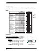
SOUNDPLUS™ INFRARED LISTENING SYSTEM SPECIFICATIONS Models WIR TX900, WIR TX925, WIR SYS 1, WIR SYS 2, WIR SYS 2P, WIR SYS 4 Two-Channel Modulator, Model MOD 232 Size, Weight: Color: Rack Mount: Power Supply: Modulation: Carrier Frequency: Signal to Noise Ratio: Frequency Response: Total Harmonic Distortion: Audio Processing: Auto Carrier Shut-Off: Power Switch: Power Indicator: Audio Level Controls: Audio Indicators: Carrier LEDs: Compress Control: Input Mix LED: Stereo LED: Phones Switch: Phones Output:
Multi–Channel Infrared Emitter, Model TX9 Dimensions, Weight: Color: Power Supply: Power Cable: Indicators: Carrier Frequency: Emitter IR Power: Coverage Area: Baseband Input: Baseband Output: Baseband Cable: Operating Requirements: Mounting Kits: Warranty: Approvals: Compatible Receivers: 11.25” W x 6.25” H x 2.125” D (28.6 cm x 15.9 cm x 5.4 cm), 1.9lbs (0.
Four–Channel Infrared Receiver, Model RX12-4 Receiver Style: Size: Weight: Color and Material: Lanyard: Operating Temperature: Battery Type: Battery Life: Battery Drain: Charging Contacts: Carrier Frequency: Operating Range: De-Emphasis: FM Deviation: Signal to Noise Ratio: Squelch: Frequency Response: Total Harmonic Distortion: Controls: Indicators: Audio Output Jacks: Audio Output Power: Acoustic Output: Sensitivity: Approvals: Warranty: Compatible Headphones/Earphones: Body-Pack, dual-lens detector, lan
® Williams Sound Helping People Hear www.williamssound.com © 2005, Williams Sound Corp.