Installation Guide & User Manual SoundPlus® Infrared Listening System Model WIR TX925, Two-Channel Listening System Model WIR TX900, Four-Channel Listening System Model WIR SYS 1, Two-Channel Listening System Model WIR SYS 3, Two-Channel Listening System Model WIR SYS 3P, Two-Channel Listening System Model WIR SYS 4, Four-Channel Listening System RoHS Modulator Model MOD 232 Emitter Model WIR TX9 Optional Receiver Models WIR RX22-4, WIR RX15-2, WIR RX18 MAN 132G
SoundPlus® Infrared Listening System Installation Guide and User Manual Contents Page System Overview.............................................................................................................................. 3 Installation Procedures MOD 232 Modulator Setup................................................................................................................. 4 Wiring & Connections.............................................................................................
System Overview The Williams Sound SoundPlus® Infrared Listening System consists of a MOD 232 Modulator(s) and one or more TX9 Emitters which use invisible infrared (IR) light to broadcast speech or music to wireless infrared receivers. The system is designed to transmit high quality audio for hearing assistance and language translation applications. Because the system uses infrared light for transmission, it is not affected by interference from radio equipment and does not interfere with radio equipment.
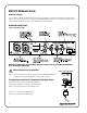
MOD 232 Modulator Setup Determine Location The modulator is usually located with the sound system amplifier or mixer for easy access to an audio input signal. For portable systems, the modulator can be placed near the emitter or in another convenient location. Infrared Stand Kits (SS-6 and SS-11) are available for portable systems.
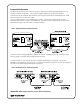
Baseband Cable Connection The MOD 232 can directly drive one or two emitters. TX9 emitters repeat the baseband signal, so any number of emitters can be used. The modulator outputs CANNOT be split with CATV splitters. Determine the length of RG-58 cable needed to reach from the TX9 Emitter to the Modulator unit. Install BNC connectors to each end of the cable.
Audio Connection Figure 5: Audio Connection Microphone Input: With the modulator DIP switches set for microphone input, the 3-pin XLR jack accepts balanced microphones. Power for condenser microphones can be selected by DIP switch. The minimum input level is 100uV and the maximum level is 90 mV. XLR Line-Level Input: With the modulator DIP switches set for line-level input, the 3-pin XLR jack accepts balanced line-level audio inputs. The minimum input level is 21mV and the maximum level is 10uV.
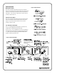
Configuration Settings Figure 8 illustrates how to configure your system using the DIP switches (Figure 7) on the back of the MOD 232 Modulator. This diagram is also printed on top of the MOD 232 Modulator unit for quick reference. Figure 7: Configuration Switches Adjust switch settings on rear of MOD 232 Modulator here: Figure 8 IMPORTANT: Channel A and Channel B must be set to different frequencies! Compressor Gain The MOD 232’s Compressor Gain is set in “Moderate” mode from the factory.
TX9 Emitter Setup TX9 Location and Placement To determine the best location for the TX9 Emitter, it helps to think of the IR emitter as an invisible floodlight. You’ll want to aim it so the listeners are “flooded” with the infrared light. Mount the emitter at least 2 ft (.61 m) above the audience. Position the emitter to face in a slightly downward angle - that will increase the “throw” of the infrared beam. Infrared light reflects off most surfaces and scatters, increasing the coverage area.
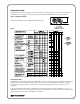
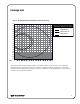
Coverage Area Figure 11: Maximum Range when using the RX22-4, RX14-2, or RX18 receiver FEET 90 Receiver Coverage Area with TX90 Transmitter in Single Channel Mode 80 70 60 RX22-4 Receiver 50 RX15-2 Receiver 40 RX18 Receiver 30 20 10 0 -10 -20 -30 -40 -50 -60 -70 -80 -90 FEET 0 10 20 30 40 50 60 70 80 90 100 110 120 130 140 150 160 These patterns are the direct radiation pattern. The infrared radiation does not drop to zero outside the illustrated patterns; it decreases.
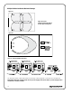
Multiple Emitters Installed to Maximize Coverage Figure 12A Figure 12A and 12B Overlapping Illumination Patterns to Cover Larger Listening Areas Figure 12B Figure 13: Connecting Multiple TX9 Emitters An unlimited number of WIR TX9 emitters can be daisy-chained together to maximize the coverage area. Remember that each emitter needs its own power supply and cannot share a power supply with a modulator or another emitter.
Compressor Gain The MOD 232’s Compressor Gain is set in “Moderate” mode from the factory. Use this setting for simultaneous interpretation. Be sure that the compress pot control, located on the front of the MOD 232 (Figure 6, page 6), is turned fully counter-clockwise. Compression can be added if desired by turning the compress pot control clockwise. For hearing assistance applications, the MOD 232’s Compressor Gain can be set to “Maximum” mode.
TX9 Features and Controls Figure 15: TX9 Emitter Rear View For use with mounting bracket.
Receiver Safety Information HEARING SAFETY CAUTION! This product is designed to amplify sounds to a high volume level which could potentially cause hearing damage if used improperly. To protect your hearing and the hearing of others: 1. Make sure the volume is turned down before putting on the earphone or headphone before adjusting the volume to a comfortable level. 2. Set the volume level at the minimum setting that you need to hear. 3.
Selector Knob Jack OFF "On" Indicator LED On/Off Volume Switch Optional Infrared Receivers RX22-4 TOP Channel Figure 13: Four Channel Receiver, Model WIR RX22-4 Frequency 1 2.3 MHz 2 2.8 MHz 3 3.3 MHz 4 3.
Trouble Shooting Neither TX9 Indicator Light Is On. XX Make sure the transformer is plugged into the emitter and any remote power switch is on. XX Make sure the electrical outlet is on. XX Make sure the 24 VAC power supply is working. Only TX9’s Power Indicator LED Comes On. XX Make sure the MOD 232 is on. XX Make sure the baseband cable is connected properly. See Figures 3 & 4. XX Check to see if the carrier light on the MOD 232 is on. XX Make sure an audio signal is being sent to the MOD 232.
Limited Warranty Williams Sound products are engineered, designed, and manufactured under carefully controlled conditions to provide you with many years of reliable service. Williams Sound warrants the SoundPlus™ Infrared Listening System against defects in materials and workmanship for FIVE (5) years. During the first five years from the purchase date, we will promptly repair or replace the SoundPlus® Infrared Listening System.
SoundPlus® Infrared Listening System Specifications Models WIR TX900, WIR TX925, WIR SYS 1, WIR SYS 2, WIR SYS 2P, WIR SYS 4 Two-Channel Modulator, Model MOD 232 Size, Weight: Color: Rack Mount: Power Supply: Modulation: Carrier Frequency: 8.5” W x 8.2” D x 1.7” H (21.5 cm x 20.8 cm x 4.4 cm), 3.1lbs. (1.
Multi–Channel Infrared Emitter, Model TX9 Dimensions, Weight: 11.25” W x 6.25” H x 2.125” D (28.6 cm x 15.9 cm x 5.4 cm), 1.9 lbs (0.
10300 Valley View Rd., Eden Prairie, MN 55344 U.S.A 800-328-6190 | 952-943-2252 | FAX: 952-943-2174 www.williamssound.