
Technical Specifications

ESR-3485
|
Most Widely Accepted and Trusted Page 2 of 5
sheets and measures 1-inch (25.4 mm) wide by
0.94-inch (23.9 mm) long by 0.060-inch (1.52 mm) deep,
with two 0.16-inch (4.06 mm) diameter holes for securing
into the post.
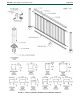
See Figure 1 for details of the components for the
aluminum railing system.
4.0 DESIGN AND INSTALLATION
4.1 Design:
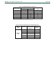
The Aluminum Railing System Series V800, C800,
M600, I800, A800, and O800 are satisfactory to resist
loads specified in IRC Table R301.5, when installed at
the maximum clear distance between the posts as noted
in Table 1. When the railing is supported on one or both
ends by the supporting structure, the maximum clear
distance between the post and the supporting structure
or between the supporting structures must comply with
the spans noted in Table 1.
4.2 Installation:
Installation must be in accordance with the
manufacturer’s published installation instructions, this
report, and guard height and opening limitations
provisions specified in IRC Section R312. The
manufacturer’s published installation instructions must
be available at the jobsite at all times during installation.
Each top and bottom rail cover snaps over the sub-rail
panel’s corresponding top and bottom h-channel rails.
The pickets are inserted into the pre-punched holes on
the top and bottom h-channel rails of the sub-rail panel.
The sub-rail panel is then attached to an extrusion post
on each end by installing top and bottom rail connector
clips with #8 x
3
/
4
-inch (19.05 mm) long stainless steel
TEK screws. Four screws (two inside and one on each
side) per each top and bottom connector clip, as shown
in Figure 1. The bottom rail connector clip must be
located 3
3
/
4
-inches (95.25 mm) from the top edge of the
clip to the bottom of the post extrusion at center. All
connector clips must be installed with two #8 x
3
/
4
-inch
(19.05 mm) long stainless steel TEK screws. Each
support leg is fastened at the midspan of the bottom rail
with one #8 x ¾-inch-long (19.05 mm) stainless steel
TEK screw. Each extruded post is attached to a post
base plate with four M8 x 80 mm long stainless steel lag
screws, which are fastened on the underside of the post
base plate, as shown in Figure 1.
5.0 CONDITIONS OF USE
The Aluminum Railing System Series V800, C800,
M600,
I800, A800, and O800 described in this report
comply with, or are a suitable alternative to what is
specified in, those codes listed in Section 1.0 of this
report, subject to the following conditions:
5.1 This product is limited to exterior or interior use as a
guardrail system for balconies, porches, and decks
for one- and two-family dwellings constructed in
accordance with the IRC.
5.2 Installation must comply with this report, the
manufacturer’s published installation instructions
and the applicable code. When the manufacturer’s
published installation instructions differ from this
report, this report governs.
5.3 Only those fasteners and fastener configurations
described in this report have been evaluated for the
installation of the Aluminum Railing System Series
V800, C800 M600, I800, A800, and O800. The
compatibility of the post base plate’s fasteners with
the supporting construction, including chemically
treated wood, is outside the scope of this report.
5.4 The Aluminum Railing System Series V800, C800,
M600, I800, A800, and O800 must be directly
fastened to supporting construction having
adequate strength and stiffness. Where required by
the code official, engineering calculations and
construction documents consistent with this report
must be submitted for approval. The calculations
must verify that the supporting construction
complies with the applicable building code
requirements and is adequate to resist the loads
imparted upon it from the products and systems
discussed in this report. The documents must
contain details of the attachment to the supporting
structure consistent with the requirements of this
report. The documents must be prepared by a
registered design professional where required by
the statutes of the jurisdiction in which the project is
to be constructed.
5.5 The top rail of the Aluminum Railing System,
for use as a handrail, is outside the scope of
this report.
6.0 EVIDENCE SUBMITTED
Data in accordance with the ICC-ES Acceptance Criteria
for Handrails and Guards (AC273), dated June 2017.
7.0 IDENTIFICATION
7.1 The Aluminum Railing System Series V800, C800,
M600, I800, A800, and O800 described in this
report are identified by a stamp, on each individual
piece or on the packaging, bearing the report
holder’s name (Ultralox), the product name
(Aluminum Railing System Series V800, C800,
M600, I800, A800, or O800), the allowable span,
and the ICC-ES evaluation report number
(ESR-3485).
Alternatively, the products described in this report
are identified by a stamp, on each individual piece
or on the packaging, bearing the additional listee’s
brand name (Williams Architectural Products or
Harmony Railing), the product name (See Table 2
of this report), the allowable span, and the ICC-ES
evaluation report number (ESR-3485).
The label shall also include the phrase “For Use
in One- and Two-Family Dwellings Only.”
7.2 The report holder’s contact information is the
following:
ULTRALOX™
2955 LONE OAK DRIVE, SUITE 180
EAGAN, MINNESOTA 55121
www.ultralox.com
7.3 The Additional listee’s contact information is the
following:
WILLIAMS ARCHITECTURAL PRODUCTS™
2955 LONE OAK DRIVE, SUITE 180
EAGAN, MINNESOTA 55121
(855) 742-7245
www.williamsrail-fence.com
HARMONY RAILING™
2955 LONE OAK DRIVE, SUITE 180
EAGAN, MINNESOTA 55121
www.harmonyrailing.com