
Technical Specifications
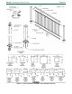
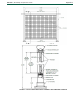
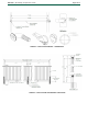
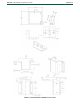
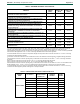
Table Of Contents

ESR-3485
|
Most Widely Accepted and Trusted Page 3 of 13
(101.6 mm) square hollow extruded 6063-T5 aluminum
with a wall thickness of 0.080-inch (2.03 mm) and come
in a powder coated finish. The post cap is produced from
A380 aluminum alloy and is installed at the top of the
extruded post and measures either
3-inches by 3-inches (76.2 mm by 76.2 mm) square or
4-inches by 4-inches (101.6 mm by 101.6mm) square.
The post base plate is produced from A369 aluminum
alloy and is installed at the bottom of the extruded post; it
comes in either a 4.02-inches (102.1 mm) by
4.02-inches (102.1) square for the 2-inches (50.8 mm)
square post or 4.99-inches (126.7 mm) by 4.99-inches
(126.7 mm) square for the 3-inches (76.2 mm) square
post. Each post base comes in a powder coated finish.
The top and bottom rail connector clips are made
from 0.080-inch (2.03 mm) thick 5052-H32 aluminum
sheets and measures 1-inch (25.4 mm) wide by
0.94-inch (23.9 mm) long by 0.060-inch (1.52 mm) deep,
with two 0.16-inch (4.06 mm) diameter holes for securing
into the post.
See Figure 2 for details of the components for the
MP400 Mesh Panel.
3.3 ADA Handrails:
The ADA Handrails consist of 1½-inch (38.1 mm) outside
diameter round hollow pipe and are produced from
extruded 6063-T5 aluminum with a nominal wall thickness
of 0.230-inch (5.8 mm). The handrail components, 90
o
wall returns and mid supports and spacers, are produced
from A369 aluminum alloy. Each handrail component
comes in a powder coated finish. See Table 1 for
maximum spans.
See Figure 3 for details of the components for the ADA
Handrails.
3.4 Aluminum Railing System with Stanchions
The Aluminum Railing System can be supported to the
substrate with stanchions into 2-inch (50.8 mm) square
aluminum posts in lieu of post base plates and consists of
guard components as described in Section 3.2. The
stanchions consist of extruded 1.715-inch wide by
1.715-inch long (43.6 mm by 43.6 mm) pieces and comes
in 20-inch long (508 mm) lengths and are produced from
6005A-T5 aluminum alloy. See Table 1 for maximum
spans.
See Figure 4 for details of guards with stanchions.
4.0 DESIGN AND INSTALLATION
4.1 Design:
The Aluminum Railing System Series V800, C800, M600,
I800, A800, O800, and L800; MP400 Mesh Panels; and
Stanchions are satisfactory to resist loads specified in
Section 1607.8.1 for the 2018, 2015 and 2012 IBC
(Section 1607.7.1 for the 2009 and 2006 IBC) and IRC
Table R301.5, when installed at the maximum clear
distance between the posts as noted in Table 1. When the
railing is supported on one or both ends by the supporting
structure, the maximum clear distance between the post
and the supporting structure or between the supporting
structures must comply with the spans noted in Table 1.
The ADA Handrails are satisfactory to resist loads
specified in Section 1607.8.1 for the 2018, 2015 and 2012
IBC (Section 1607.7.1 for the 2009 and 2006 IBC) and
IRC Table R301.5. The maximum clear distance between
the supports is 72 inches (1828 mm); see Table 1 for
maximum spans.
4.2 Installation:
Installation must be in accordance with the
manufacturer’s published installation instructions, this
report, and guard height and opening limitations
provisions specified in Sections 1014 and 1015 of the
2018 and 2015 IBC (Sections 1012 and 1013 of the 2012,
2009 and 2006 IBC) and Sections R311 and R312 of the
IRC, as applicable. The manufacturer’s published
installation instructions must be available at the jobsite at
all times during installation.
Each top and bottom rail cover snaps over the sub-rail
panel’s corresponding top and bottom h-channel rails.
The pickets are inserted into the pre-punched holes on
the top and bottom h-channel rails of the sub-rail panel.
Consisting of either picket in-fill panel or MP400 mesh
panel, the sub-rail panel is then attached to an extrusion
post on each end by installing top and bottom rail
connector clips with #8 x
3
/
4
-inch (19.05 mm) long
stainless steel TEK screws. Four screws (two inside and
one on each side) per each top and bottom connector clip,
as shown in Figure 1. The bottom rail connector clip must
be located 3
3
/
4
-inches (95.25 mm) from the top edge of
the clip to the bottom of the post extrusion at center. All
connector clips must be installed with two #8 x
3
/
4
-inch
(19.05 mm) long stainless steel TEK screws. Each
support leg is fastened at the midspan of the bottom rail
with one #8 x ¾-inch-long (19.05 mm) stainless steel TEK
screw. Each extruded post is attached to a post base
plate with four M8 x 80 mm long stainless steel lag
screws, which are fastened on the underside of the post
base plate, as shown in Figure 1. The post base plate
must be fastened to the supporting wood substrate with a
minimum specific gravity of 0.50 using either four –
3
/
8
-inch x 6-inch long (9.5 mm x 152.4 mm) GRK RSS
wood screws or four –
5
/
16
-inch x 6-inch long (7.9 mm x
152.4 mm) GRK RSS wood screws. When the supporting
substrate is concrete having a minimum compressive
strength of 3700 psi (25.5 MPa), each post base plate
must be fastened to the supporting concrete substrate
using four ¼-inch x 3-inch long (6.35 mm by 76.2 mm)
corrosion resistant coated concrete anchor bolts.
When the optional 4-inches (101.6 mm) square post
sleeve is installed over an existing nominal 4-by-4
(101.6 mm x 101.6 mm) wood post, all wood post fastener
connections to the supporting substrate and sub-rail
connections through the post sleeve to the wood post
must be designed by a registered design professional.
ADA Handrails must have each support attached to the
supporting wood substrate with a minimum specific
gravity of 0.49. Each 90
o
Wall Return and mid support is
fastened to the wood substrate using three –
5
/
16
-inch x
4 inch-long (7.9 mm by 101.6 mm) construction lag
screws. When each 90
o
Wall Return and mid support is
fastened to 3-inches (76.2 mm) square hollow extruded
6005A-T5 aluminum with a wall thickness of 0.065-inch
(1.65 mm), each connection must use three – #10 x
1½-inch long (38.1 mm) stainless steel TEK screws.
When stanchions are used to support 2-inch
(50.8 mm) square aluminum posts in lieu of post base
plates, the 2-inch (50.8 mm) square post must fit over
each stanchion at a maximum length of 14.75 inches
(374.6 mm). The connections of the stanchion to the
stanchion mount and the mount to the supporting
structure must be designed by a registered design
professional.