
User Manual

UnDerstanDIng ParametrIc DesIgn
|
9
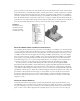
game, you had to knock down all of the bottles. However, if the bottle in the center on the bottom
were nailed down, it would be impossible to win the game, and as a matter of physics, it would be
difficult to knock down the bottles next to it. Having a grounded component in your assemblies,
one that is “nailed down,” will likewise keep your assemblies from falling over as you build on to
them. By default, the first component you place into an empty assembly file will automatically be
grounded. You can unground it and ground another if need be, but you should always maintain at
least one grounded component. You can also have more than one grounded component.
ma K e yo u r mo D e l s mi m i c t h e ma n u F a c t u r i n g pr o c e s s
The simplest advice that new users can receive on the subject of assemblies is to structure them
as you would in real life. If in the design you plan to assemble several parts into a transmission
and then drop that transmission into a housing, then you should make the transmission a sub-
assembly and insert it into the upper-level housing assembly. Alternatively, a new user might
place all of the parts into one big assembly, only to later realize that subassemblies are needed
for the purpose of getting the bill of materials organized. By making your models mimic the
manufacturing process, you can also find possible flaws in your design, such as fasteners that
cannot be accessed or areas where parts may interfere with each other during assembly.
In some instances a model will be developed in the research and development (R&D)
department and then handed to the manufacturing engineering (ME) department to be built.
Although the folks in R&D may enjoy the freedom of “dreaming up” anything they can think
of, an effective R&D designer will always have one eye on what can actually be built within the
capabilities of the shop floor. Keep this in mind during the initial development cycle, and it will
prevent those downstream from having to re-create much of your work. However, if restruc-
turing the components into more or fewer subassemblies is required after the initial design,
Inventor has demote and promote tools to assist with that. These tools will be covered in the
chapters to come.
co n s t r a i n t o or i g i n ge o m e t r y
As mentioned earlier in this chapter, each part file has default origin geometry built in. You
should build parts around the origin geometry whenever possible. For instance, a transmission
has gears, bearings, seals, and so on that are all concentric with the shaft. If you model all the
parts so their x-axes will be aligned in the assembly, then you can use the x-axis of each part
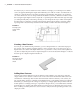
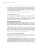
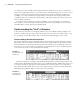
Figure 1.7
The Model browser
showing the model
tree of an assembly
named Router.iam
016824c01.indd 9 4/29/11 6:56:14 AM