
User Manual
UnDerstanDIng ParametrIc DesIgn
|
7
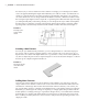
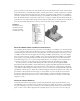
rectangles dimensioned at an angle defines the basic shape and is much easier to sketch and
fully constrain than the finished shape would be.
If the idea of simple sketches seems not to fit the type of design you do, understand that most
any design will benefit from the simple-sketch philosophy. More important, if you start out
employing simple sketches, you will more quickly master the sketch tools and then be ready to
create more-complex sketches when a design absolutely requires it.
cr e a t e si m p l e Fe a t u r e s F r o m si m p l e sK e t c h e s
Another aspect of creating simple sketches is that it allows you to create simple features.
Parametric feature-based modeling relies on the creation of numerous simpler features within
the model to achieve a complex design in the end. By creating a number of features within the
model, you are able to independently change or modify a feature without rebuilding the entire
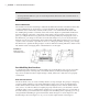
model. An example of editing a feature would be changing a hole size. If you create a base
feature first and then create a hole feature in that base feature, you can make changes to both
independently.
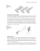
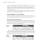
pa t t e r n a n D mi r r o r a t t h e Fe a t u r e le v e l
Although there are mirror and pattern (array) tools in the sketch environment, it is generally
best to create a single instance of the item in the sketch and then create a feature from it and
create a mirror or pattern feature from that feature. The logic behind this is based on the idea of
keeping sketches simple and the anticipation of future edits. Should the mirror or pattern fea-
ture need to be updated, it is much easier to update it as a separate feature.
cr e a t e sK e t c h -Ba s e D Fe a t u r e s a n D th e n pl a c e D Fe a t u r e s
Part features can be separated into two categories: sketch-based and placed. Sketch-based features,
as you might guess, are created from sketches. Placed features are features such as fillets and
chamfers that are placed by using model edges or faces and have no underlying sketch. Issues
arise when placed features are created too early in the development of the part because you
may then be required to dimension to the placed feature, which creates a weak dependency.
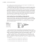
For instance, you might place rounded fillet features along the edges of a part and then use the
tangent fillet edges to define the placement of a hole. But then if you realize that machining
capabilities require a beveled chamfer edge rather than a rounded filleted one and delete the fil-
let feature, the hole feature is sure to fail because the tangent fillet edges used to define the hole
placement no longer exist. Keep this in mind as you create placed features such as fillets and
chamfers, and reserve placed features for the end stages of the part.
un D e r s t a n D De p e n D e n t a n D in D e p e n D e n t Fe a t u r e s
Parametric model features are typically either dependent or independent of one another. A
dependent feature is dependent on the existence or position of a previously created feature. If
that previously created feature is deleted, then the dependent feature will either be deleted also
or become an independent feature. As mentioned earlier, each part file contains default origin
geometry defining the x-axis, y-axis and z-axis of the part. These origin features are used to
create the first sketch in every part by default. An independent feature is normally based on an
origin feature or is referenced off the base feature.
016824c01.indd 7 4/29/11 6:56:14 AM