
User Manual
UnDerstanDIng ParametrIc DesIgn
|
5
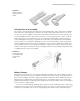
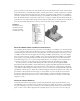
X Axis, the axis running in infinitely in the X direction•u
Y Axis, the axis running in infinitely in the Y direction•u
Z Axis, the axis running in infinitely in the Z direction•u
Center Point, the point found at zero in the X, zero in the Y, and zero in the Z directions•u
When creating the base sketch of a part file, you typically start on one of the origin planes.
Because the origin plane cannot be edited, deleted, redefined, or upset in any manner, this base
sketch is inherently stable, and as a result, the base feature you create from it is stable as well.
If the second sketch of your part is created on a 3D face of the base feature, then this sketch is
dependent upon the base sketch and is considered slightly less stable than the base sketch. This
is because the base sketch could be edited, deleted, or redefined in a way that would upset the
secondary sketch.
Understanding how dependencies are created when a sketch and features are based on one
another will help you avoid creating a “house of cards” that will fall apart if the base is upset.
Although you could base all of your sketches and features on origin geometry to minimize
dependencies, it is generally not practical to do so. It should be your goal, however, to keep the
number of chained dependencies to a minimum. Assemblies work in much the same way, using
the faces and edges of parts to constrain them together and as a result building dependencies
between them. Just like part files, assembly files have origin planes, axes, and a center point that
can be used to minimize chained dependencies, thereby creating a more stable model.
Looking Closer at Sketch Dimensions
A large part of creating a stable sketch is understanding the way Inventor’s sketch dimensions
work. To do so you might compare Inventor dimensions with AutoCAD’s standard dimensions.
When you created a design in AutoCAD, that design process was not much different from cre-
ating the same design on a drawing board. But in AutoCAD, you can draw precise lines, arcs,
circles, and other objects and place them precisely and with accurate dimensions reflecting your
design in a way that you cannot do by hand. When a design requires modification, you erase,
move, copy, stretch, and otherwise manipulate the existing geometry more quickly than you
can by hand as well. But other than those gains in speed and accuracy, the workflow is much the
same as working on a drafting board. In short, AutoCAD automates drafting tasks but does less
to speed up and enhance the design process.
Dr i v e n Di m e n s i o n s
Standard dimensions in AutoCAD are called driven or reference dimensions. A driven dimen-
sion is controlled by the geometry, and it reflects the actual value of the geometry being refer-
enced by the dimension. If you stretch a line, for example, the dimension attached to the line
will update to the new value. If you think about it, the only reason for a dimension on a typical
AutoCAD drawing is to convey the value of a feature or part to the person who is going to build
it. If you import that 2D file into a Computer Aided Manufacturing (CAM) software, no dimen-
sions are needed because the line work contains all the information about the part.
016824c01.indd 5 4/29/11 6:56:14 AM