
User Manual


4
|
CHAPTER 1 Inventor DesIgn PhIlosoPhy
How would the holes be affected? Should they stay in the same place? Or should they stay at
some defined distance from one end or the other?
Anticipating changes to the model is a large part of being successful with Inventor. Imagine,
for instance, that a simple design change required that the pivot link become 50 millimeters lon-
ger on one leg. This should be a simple revision that requires you only to locate the dimension
controlling that leg length and change the parameter value. Unfortunately, if you did not follow
the best-practices guidelines when creating the part originally, the change in the length might
displace the secondary features such as holes and material cuts and require you to stop and fix
each of those as well. This is one of the most frustrating parts of learning Inventor for any new
user who has not taken the time to learn or follow the known best practices of parametric mod-
eling. Fortunately for you, within the pages of this book you will learn how to create models
that are easy to update and do not “fall apart” during design changes.
Understanding History-Based Modeling and Dependencies
Inventor is often referred to as a history-based modeler, meaning that as you create sketches
and turn them into features and then add more features and still more features, each addition
is based on a previous feature, and so the model is said to have history. This history is recorded
and tracked in the Model browser. The Model browser is a panel that displays on-screen and
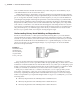
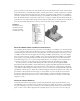
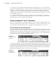
shows every feature you create during the design of your part. Figure 1.5 shows the Model
browser for the pivot link file.
You can see that each feature is listed in the browser in the order in which it was created,
forming a history tree. To create a part that handles changes predictably, you must create a solid
foundation on which to build the rest of the model. In most cases, when you are designing a part
model you will start with a sketch, much like the one shown back in Figure 1.1. This base sketch
will be your foundation, and therefore you must create it to be as stable as possible.
Each part, no matter what it is or what it looks like, has a set of origin geometry in the
form of the origin planes, origin axes, and a single origin point. You can find these origin
features by expanding the Origin folder in the Model browser. Figure 1.5 shows the Origin
folder not expanded. If you expand the Origin folder in any part or assembly file, you see the
following items:
YZ Plane, the plane that runs infinitely in the Y and Z directions
•u
XZ Plane, the plane that runs infinitely in the X and Z directions•u
XY Plane, the plane that runs infinitely in the X and Y directions•u
Figure 1.5
The Model browser
showing the fea-
ture tree (history)
of a part named
Pivot_Link.ipt
016824c01.indd 4 4/29/11 6:56:14 AM