
User Manual


24
|
CHAPTER 1 Inventor DesIgn PhIlosoPhy
Four Ways to Use EOP Markers
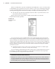
Because part features are listed sequentially, in the order they were created, the EOP marker allows
you to figure out how a part was constructed. It can also be used to reorder features, repair a part,
and compress a file size for emailing or posting online. Here are four ways to use EOP markers:
Dragging the EOP marker to the top and then dragging it down one feature at a time re-creates
•u
the part. This can be useful when working with parts designed by others and can be used as a
powerful learning tool.
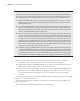
You can use the EOP marker to insert a feature anywhere in the model tree. For instance, if you •u
meant to create a hole before creating a rectangular cut, you could use the EOP marker to sus-
pend the rectangular cut feature and then place the hole feature. Then to bring the rectangular
cut back, move the EOP marker back to the bottom.
Because part features are based hierarchically in that one is based on another, oftentimes a
•u
change to a primary feature will break a secondary one, which in turn breaks another, and
another, and so on. The cascade of errors down through the feature tree can be intimidating
and appear to the new user as if every single feature will need to be rebuilt. In most cases,
though, if you move the EOP marker up to just below the first errant feature and then fix it, the
following feature will be fixed as well. If not, you can repair it and step down to the next one,
and the next one, until all are healthy again. Using the EOP marker to fix features in the order
they were created is the best way to approach the task.
In addition, dragging the EOP marker to the top of the part file and leaving it there reduces the
•u
overall part size significantly. This is a good way to reduce a file size if you need to email a part file
to someone. When they receive it, they can just drag the EOP marker down and then see the part
as you designed it. Likewise, if you encounter a blank file in your modeling session, be sure to check
the Model browser to make sure the EOP marker has been dragged to the bottom of the part file.
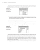
5. Next double-click the icon for Extrusion1 in the faceplate feature tree (or right-click
Extrusion1 and choose Edit Feature). This activates the feature for editing.
6. Replace the value 0.5 in with 5 mm, taking care to enter the unit suffix mm in lowercase
letters, and then click OK and you’ll see your edits take place.
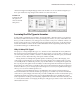
7. To have a closer look at the change, select the face on the ViewCube marked Right. Then
place your cursor over the faceplate in the graphics screen and use your mouse wheel
to zoom in to the faceplate. Note that you zoom to wherever your cursor is pointing
on-screen.
You will see that the change has created a gap between the faceplate and the end of the frame
of the press, as shown in Figure 1.21.
Now that your part feature is edited, leave the part level and return to the assembly level
where you started out.
8. On the Model tab, click the Return button on the far right.
016824c01.indd 24 4/29/11 6:56:25 AM