
User Manual


UsIng the Inventor graPhIcal InterFace
|
23
eD i t a pa r t
You’ll continue with the exploration of the browser by setting a part file active for edits and
making a change to a part feature:
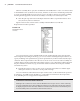
1. In the browser, double-click the part called Face_Plate_mi_1 to set it active for edits. If
you hover for a moment over the icon, the plus sign may automatically expand; you can
disregard that and just double-click the icon.
Note that it is best practice to get into the habit of double-clicking the icon next to the com-
ponent name rather than the name itself because clicking the latter may initialize an edit of just
the name, depending upon the speed of your clicks. Double-clicking the icon will activate the
component for editing in place, within the assembly. Once a component is activated, all other
portions within the Model browser will be grayed out. With the faceplate part activated, you
will notice that the Model tab becomes active in the Ribbon menu and the Model browser shows
all the features of the faceplate. Both changes reflect that you are now editing a part file and are
therefore working at the part editing level of the model hierarchy, with part feature tools ready
for selection.
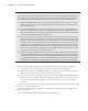
Examining the features within the active part, you can see a folder named Solid Bodies, the
standard Origin folder, and then all of the features that were created to make the faceplate, such
as extrusions, holes, fillets, and so on. You will also notice a red X at the bottom of the part, sig-
nifying the end-of-part (EOP) marker.
Controlling Component Transparency
It is generally helpful to set the display settings so that as you activate one component in the context
of an assembly, the other components become ghosted, or transparent. This allows you to see which
component you’re actively editing and yet still reference other components in the assembly. You
can toggle the Transparency setting on and off by clicking the Component Transparency drop-down
found on the Appearance panel in the View tab.
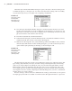
2. Click and hold the EOP marker and drag it up the model tree until you see a black bar
above Extrusion1, and then drop it there.
You should see all of the features become grayed out in the browser and the faceplate disap-
pear in the graphics area. Essentially, you have rolled back the history of the faceplate to before
it contained any features.
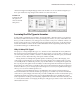
3. To bring the features back, click and hold the EOP marker and drag it until you see a
black bar under Extrusion1, and then drop it there. You’ll see this base feature become
visible again.
4. Do this for each feature in the tree, and you will step through the sequence of features
and get an idea of how the faceplate was created. Note that some features are on the back
side of the faceplate, so you may not see them, depending upon your viewing angle.
Ensure that you have the EOP marker back at the very end of the part (below Fillet3)
before continuing to the next step.
016824c01.indd 23 4/29/11 6:56:24 AM