
User Manual

2
|
CHAPTER 1 Inventor DesIgn PhIlosoPhy
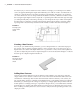
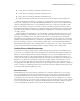
For instance, if you were to sketch four lines to define a rectangle, you would expect two dimen-
sions to be applied, defining the length and width. But you would also need to use 2D sketch con-
straints to constrain the lines so that they would stay perpendicular and equal to one another if
one of the dimensions were to change. Without the sketch constraints, a dimensional edit to make
the rectangle longer might result in a trapezoid or a parallelogram rather than the longer rectangle
you anticipated. By fully constraining a sketch, you can anticipate the way in which it will update.
Inventor helps you with this concept by automatically applying many sketch constraints and by
reporting when a sketch is fully constrained. This will be covered in more detail in Chapter 3.
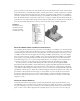
Creating a Base Feature
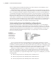
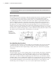
Not only do you add 2D sketch parameters; you also add parameters to control the 3D proper-
ties of parts. This is done by using the sketch to create a feature such as an extrusion to give a
depth value to the sketch. The depth dimension is a parameter as well, and it can be updated at
any time to adjust the part model as required. Figure 1.2 shows the sketch from Figure 1.1 after it
has been given a depth using the Extrude tool.
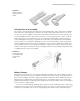
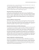
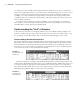
Adding More Features
Once the part is three dimensional, more sketches can be added to any of the faces of the 3D
shape, and those new sketches can be used to create some feature that further defines the form
and function of the design. The model is then enhanced with more features, such as holes, fil-
lets, and chamfers, until it is complete. Each added feature is controlled by still more parameters
defined by you, the designer. If a change is required, you simply update the parameter and the
model updates accordingly. This type of parametric design allows you to build robust and intel-
ligent models very quickly and update them even faster. Figure 1.3 illustrates the typical work-
flow of adding secondary features to a base feature to fully realize the part design, in this case a
simple pivot link.
Figure 1.1
Creating a para-
metric model
sketch
Figure 1.2
A basic part model
created from the
sketch
016824c01.indd 2 4/29/11 6:56:13 AM